Wireless antenna for emitting conical radiation

a technology of conical radiation and wireless antennas, which is applied in the direction of antennas, electrical equipment, radio transmission, etc., can solve the problems of increasing radiation provided to the user and reducing so as to increase the radiation provided and reduce the power used by the wireless router

Inactive Publication Date: 2010-05-13
MICROSOFT TECH LICENSING LLC
View PDF11 Cites 163 Cited by
  • Summary
  • Abstract
  • Description
  • Claims
  • Application Information

AI Technical Summary

Benefits of technology

[0006]The antenna described above can be positioned adjacent to three other substantially similar antennas in a cross-like configuration to provide for three hundred and sixty degree coverage. For instance, the reflector elements of each of the four antennas can be positioned towards a center of the cross-like configuration. Each of the antennas can direct radiation to an approximately ninety degree area of coverage. Accordingly, excitation current can be selectively provided to a subset of the four antennas to provide radiation to a particular area (e.g., where less than three hundred and sixty degree coverage is needed). In an example, a user employing a portable computing device may desirably receive radiation from a wireless router that includes the four antennas. The user may be positioned relative to the wireless router such that only one of the four antennas is needed to provide radiation to the user. Thus, excitation current can be selectively provided to one of the antennas in the wireless router while not provided to the other three antennas in the wireless router, which increases gain of radiation provided to the user and reduces power used by the wireless router.

Problems solved by technology

Thus, excitation current can be selectively provided to one of the antennas in the wireless router while not provided to the other three antennas in the wireless router, which increases gain of radiation provided to the user and reduces power used by the wireless router.

Method used


Image

  • Wireless antenna for emitting conical radiation
  • Wireless antenna for emitting conical radiation
  • Wireless antenna for emitting conical radiation

Examples


Embodiment Construction

[0017]Various technologies pertaining to wireless communications will now be described with reference to the drawings, where like reference numerals represent like elements throughout. In addition, several functional block diagrams of example systems are illustrated and described herein for purposes of explanation; however, it is to be understood that functionality that is described as being carried out by certain system components may be performed by multiple components. Similarly, for instance, a component may be configured to perform functionality that is described as being carried out by multiple components.

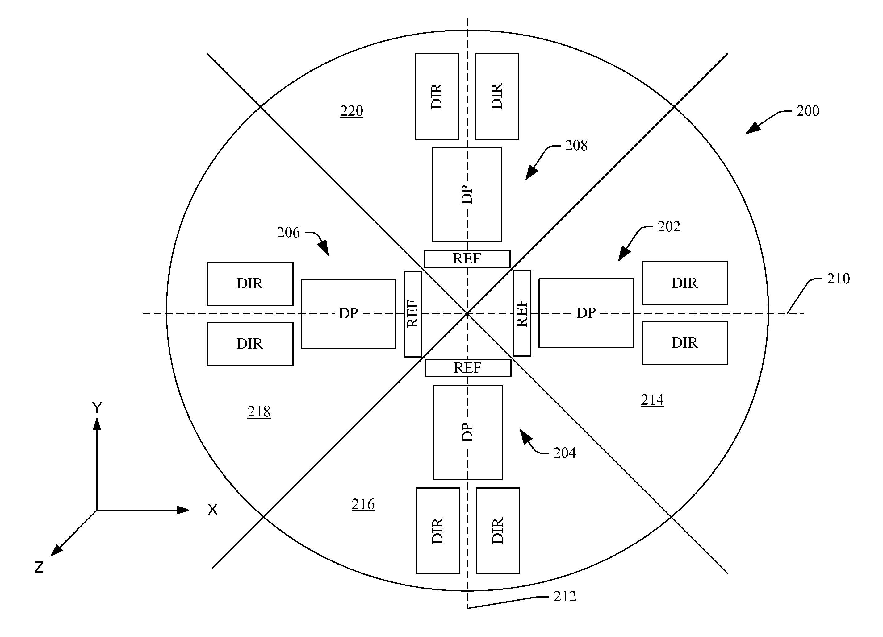
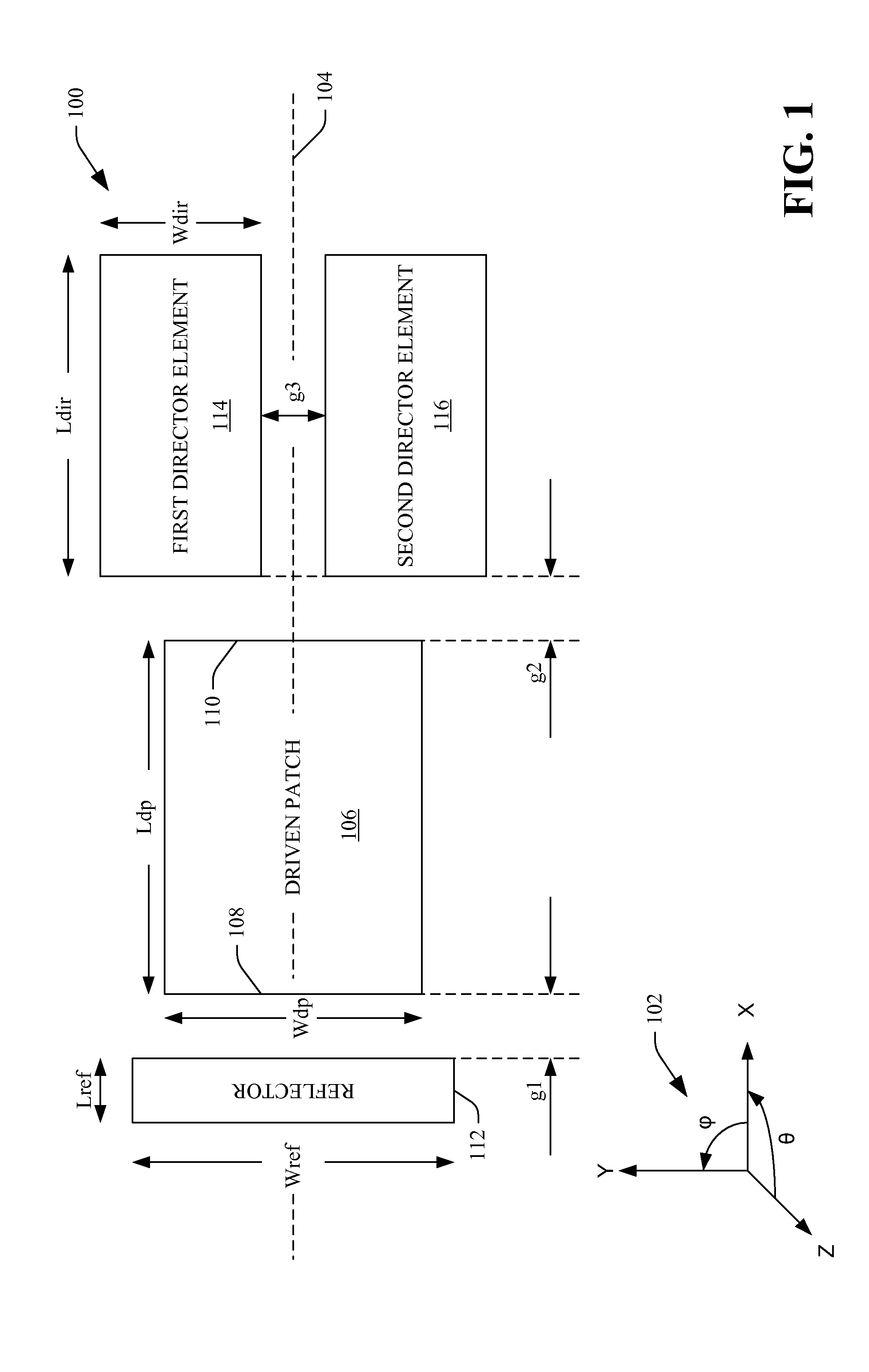
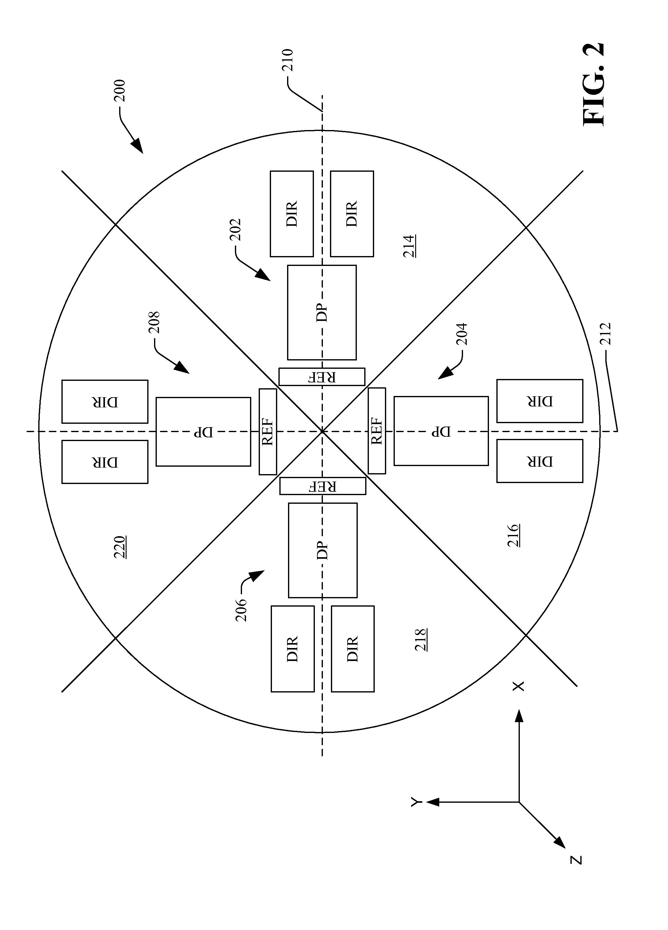
[0018]With reference to FIG. 1, an example antenna 100 is illustrated. The antenna 100 can be used in various wireless communication devices, including but not limited to a wireless router, a gaming system, a cellular telephone transmission tower, or other suitable wireless communications device that transmits wireless signals. The antenna 100 can be a planar antenna that is ...


PUM


Abstract

An antenna described herein includes a driven patch that is configured to emit radiation in a broadside direction in response to receiving excitation current, wherein the driven patch has a first radiating edge and a second radiating edge that are approximately parallel to one another. The antenna also includes a reflector element that is configured to reflect radiation emitted from the first radiating edge in a quasi-endfire direction. The antenna can also include two director elements that are configured to direct radiation emitted from the second radiating edge of the driven patch in a quasi-endfire direction.

Description

BACKGROUND[0001]The use of wireless technology has become prevalent in today's society. For instance, many individuals use cellular phones to communicate with others. Some cellular phones are also equipped with applications that allow users to have immediate access to their email as well as the Internet, thereby allowing the user to, for instance, access the latest news, check stock quotes, and perform other activities. Furthermore, many homes, businesses and workplaces have become equipped with wireless networks that enable users to connect to an intranet and / or the Internet.[0002]In still yet another example, gaming systems can be equipped with wireless capabilities such that users of a gaming system can employ controllers that are in wireless communication with a gaming device. For instance, depression of a button or a particular motion can be transmitted from a controller to the gaming system.[0003]When transmitting or receiving data by way of a wireless connection, antennas are...

Claims


Application Information

Patent Timeline
Patent Type & Authority Applications(United States)
IPC IPC(8): H01Q15/14H04B7/24
CPCH01Q9/0407H01Q19/28H01Q19/10
Inventor DEJEAN, II, GERALD REUBEN
Owner MICROSOFT TECH LICENSING LLC
Why Eureka
Try Eureka