Eureka AIR delivers breakthrough ideas for toughest innovation challenges, trusted by R&D personnel around the world.

Storage Control Device

Inactive Publication Date: 2010-05-13
HITACHI LTD
View PDF10 Cites 45 Cited by
  • Summary
  • Abstract
  • Description
  • Claims
  • Application Information

AI Technical Summary

Benefits of technology

[0008]The present invention has been made in consideration of the problems described above, and its object is to provide a storage control device which can provide a greater storage capacity, and which moreover can be effectively cooled. Another object of the present invention is to provide a storage control device which can enhance the cooling performance and the operability of a storage unit which has a plurality of sub-storage units. Yet further objects of the present invention will become clear from the following description of embodiments thereof.

Problems solved by technology

However, the more extension chassis are added, the more does the size of the storage control device increase.
Furthermore, if the number of storage devices which are provided in the extension chassis is increased, the amount of heat which is generated also increases.
Accordingly, although it is necessary to obtain a draft of cooling air which is matched to this amount of heat, if simply the rotational speed of a cooling fan is increased, then the noise also becomes great.
Due to this, the flow of the draft of cooling air changes, and there is a possibility that the cooling air draft will not be adequately supplied to at least some of the storage devices, so that they will not be properly cooled.
In particular, for example with the so called drawer method which makes it possible to take out a storage device or the like from the upper surface of a chassis like a drawer and to put it back in, if maintenance work is to be performed without stopping the operation of the storage control device, then the above described problem of the cooling air draft appears prominently.
Accordingly, it is not possible to perform maintenance work over a long time period, i.e. it is necessary to complete any maintenance work in a short time period, so that the convenience of use decreases.
This is because, the longer becomes the time period over which the lid unit is removed, the more does the temperature of the storage device or devices to which the cooling air draft is not adequately supplied become elevated, so that it is possible for problems due to high temperature to occur.

Method used


Image

  • Storage Control Device
  • Storage Control Device
  • Storage Control Device

Examples


embodiment one

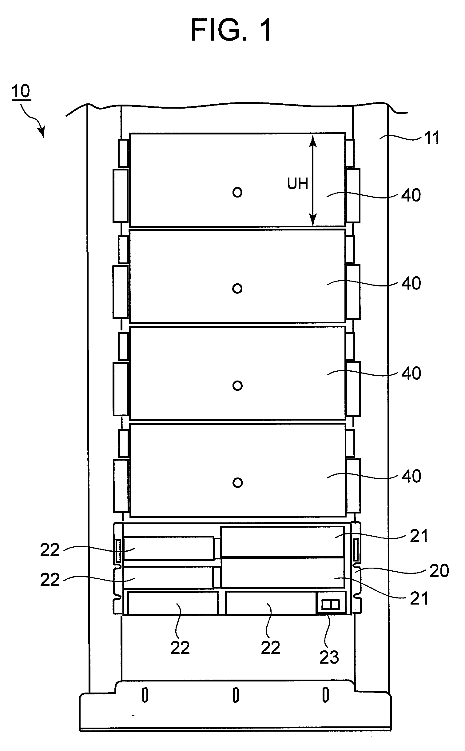
[0057]A first embodiment will now be explained on the basis of FIGS. 1 through 33. FIG. 1 is an elevation view of the storage control device 10. One control unit 20 and a plurality of storage units 40 are removably fitted In a rack 11 which is built, for example, as a 19 inch rack.

[0058]The control unit 20, which serves as a “control device”, is a device for controlling the storage control device 10, and is, for example, fitted at the lower portion of the rack 11. The structure of this control unit 20 will be described hereinafter with reference to FIG. 3. To explain the control unit 20 as far as it is shown in FIG. 1, in addition to a controller 30 which will be described hereinafter, it also comprises, for example, a plurality of cooling fans 21, a plurality of battery devices 22, and a main switch 23. The cooling fans 21 are fans for cooling the control unit 20. The battery devices 22 supply battery power to the control unit 20 and the storage units 40 during interruptions of mai...

embodiment two

[0173]A second embodiment will now be explained with reference to FIGS. 33 and 34. This embodiment corresponds to a variant of the first embodiment described above. Accordingly, the explanation will focus upon the points of difference from the first embodiment. The distinguishing feature of this embodiment is that the front cover 44F is divided into two parts, i.e. a left part and a right part, corresponding to the two sub-storage units 50L and 50R.

[0174]FIG. 34 is a perspective view of a storage unit fitted to a rack, according to this second embodiment

[0175]As shown in the perspective view of FIG. 35, the user is able to perform maintenance work by taking off from the case 41 only that cover which corresponds to the desired sub-storage unit. In the example shown in FIG. 35, the situation is shown in which the left side cover 44FL is removed, so that maintenance work may be performed upon the sub-storage unit 50L.

[0176]With this embodiment having this structure, similar advantageou...


PUM


Abstract

With the storage control device of the present invention, it is possible to mount a larger number of storage devices and to cool them effectively. A plurality of sub-storage units are provided within one storage unit. Each sub-storage unit includes a plurality of hard disk drives, a plurality of enclosures, and a plurality of power supply devices. A cover is divided into a front cover which covers over the front side of a case, and a rear cover which covers over the rear side of the case. Shield portions are provided on the upper sides of the hard disk drives and the enclosures. By these shield portions contacting the adjacent modules (other disk drives and other enclosures), it is possible to reduce the negative influence upon cooling air draft passages within the case, even when a cover has been removed.

Description

CROSS-REFERENCE TO RELATED APPLICATIONS[0001]This application relates to and claims priority from Japanese Patent Application No. 2008-290062 filed on Nov. 12, 2008, the entire disclosure of which is incorporated herein by reference.BACKGROUND OF THE INVENTION[0002]The present invention relates to a storage control device.[0003]A storage control device is a device which supplies a storage region of comparatively large capacity to a host computer (hereinafter termed a “host”). A storage control device may, for example, construct a storage region on the basis of RAID (Redundant Array of Independent Disks), using a plurality of hard disk drives. Logical volumes, which are logical storage regions, are established over the physical storage regions possessed by the hard disk drives. The host is able to perform reading and writing of data to and from these logical volumes.[0004]Now, a storage control device is per se known (see JP-A-2007-011682) in which a main chassis which is in charge o...

Claims


Application Information

Patent Timeline
IPC IPC(8): G06F1/20H05K7/14H05K5/02
CPCH05K7/20736G06F1/20
Inventor SASAGAWA, TSUYOSHIINAMURA, AKIHIROARIKAWA, REISHIMOKAWA, MINORUHONDA, KIYOSHI
Owner HITACHI LTD
Why Eureka
Eureka Blog
Learn More