
Optical information recording apparatus, optical information recording method, optical information reproducing apparatus, optical information reproducing method, and optical information recording medium

Inactive Publication Date: 2010-05-13
SONY CORP
View PDF6 Cites 1 Cited by
  • Summary
  • Abstract
  • Description
  • Claims
  • Application Information

AI Technical Summary

Benefits of technology

[0016]Accordingly, the optical information reproducing method can reproduce main data according to the presence or absence of a record mark to be detected with modulated information light, and reproduce sub-data according to the presence or absence of a deviation of the center of the record mark from the irradiation line.
[0018]Accordingly, the optical information recording medium makes it possible to reproduce main data according to the presence or absence of a record mark, and to reproduce sub-data according to the presence or absence of a deviation of the center of the record mark from an irradiation line.
[0022]Accordingly, the optical information reproducing apparatus can implement focusing control using servo light that is unsusceptible to a deviation of the center of a record mark from an irradiation line, and can therefore reliably detect the presence or absence of the deviation representing sub-data by reliably irradiating information light to the irradiation line.
[0024]Accordingly, in the optical information recording medium, focusing control that employs servo light unsusceptible to a deviation of the center of a record mark from an irradiation line can be implemented. Therefore, the information light can be reliably irradiated to the irradiation line, and the presence or absence of the deviation representing sub-data can be reliably detected from the modulated information light.
[0030]Further, according to the present invention, there is provided an optical information recording medium in which since focusing control employing servo light unsusceptible to a deviation of the center of a record mark from an irradiation line can be implemented, information light can be reliably irradiated to an irradiation line, the presence or absence of the deviation which represents sub-data can be reliably detected from the modulated information light, and the sub-data can be reproduced.

Problems solved by technology

However, a method of recording or reproducing sub-data in the same manner as the conventional optical disk drive does has not been proposed.

Method used


Image

  • Optical information recording apparatus, optical information recording method, optical information reproducing apparatus, optical information reproducing method, and optical information recording medium
  • Optical information recording apparatus, optical information recording method, optical information reproducing apparatus, optical information reproducing method, and optical information recording medium
  • Optical information recording apparatus, optical information recording method, optical information reproducing apparatus, optical information reproducing method, and optical information recording medium

Examples


first embodiment

(1) First Embodiment

(1-1) Construction of an Optical Disk

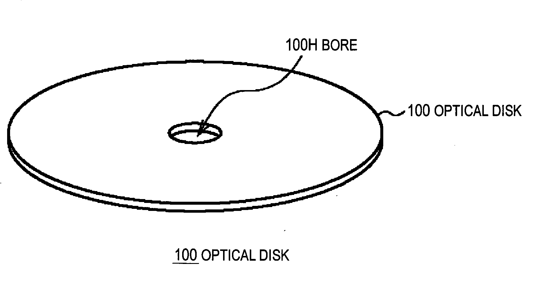
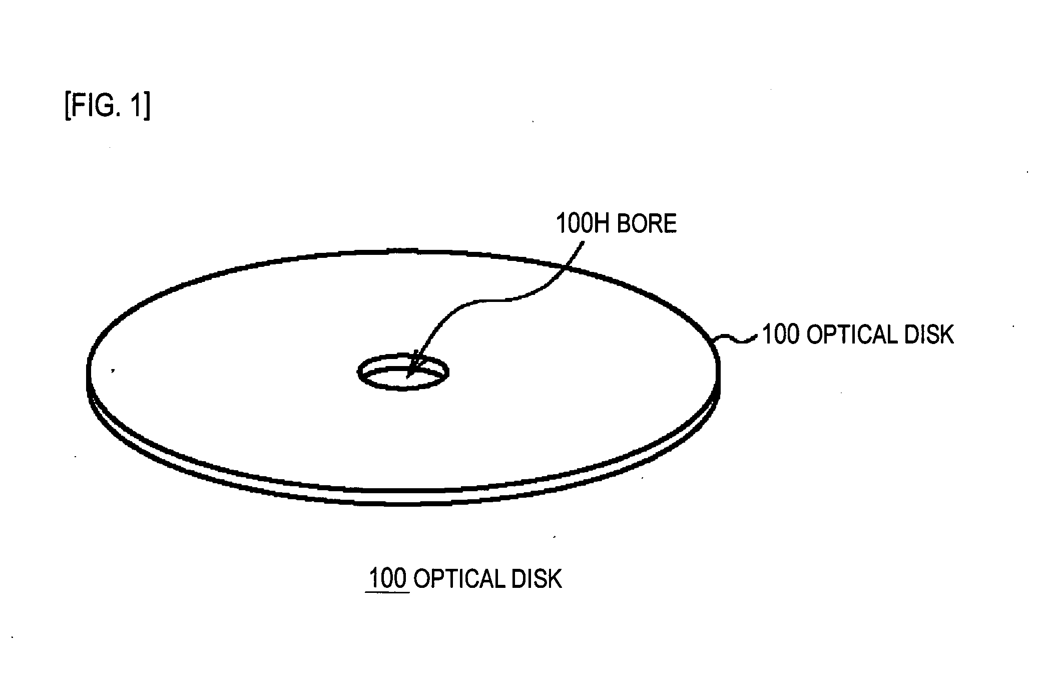
[0054]To begin with, an optical disk 100 employed as an optical information recording medium in the present invention will be described below. As seen from the appearance diagram shown in FIG. 1, the optical disk 100 is formed like a disk, which has a diameter of approximately 120 mm, as a whole similarly to the conventional CD, DVD, and BD, and has a bore 100H in the center thereof.

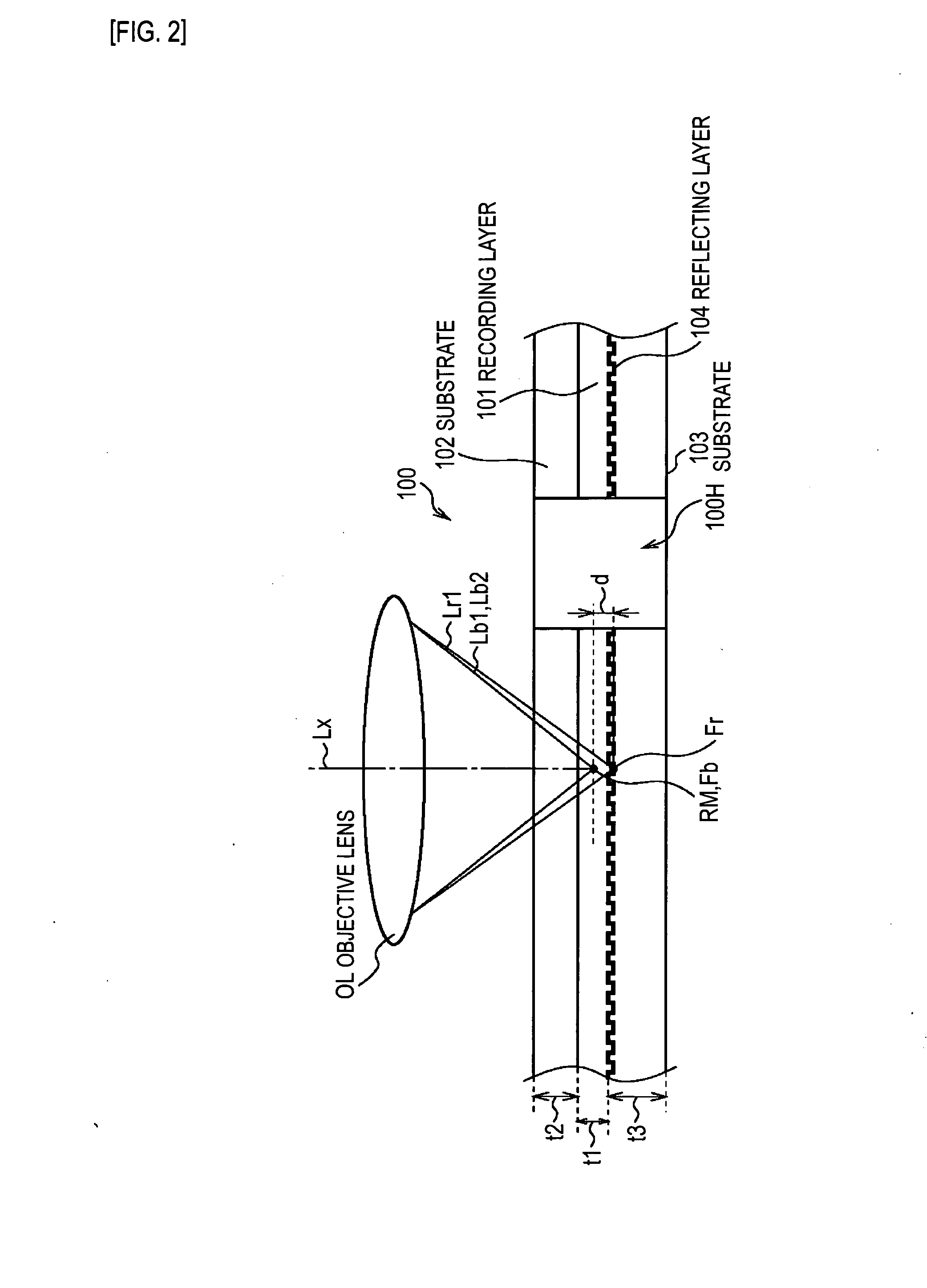
[0055]The optical disk 100 includes, as seen from the sectional view shown in FIG. 2, a recording layer 101, in which, information is recorded, in the center thereof, and has the surfaces of the recording layer 101 sandwiched between substrates 102 and 103.

[0056]Incidentally, the thickness t1 of the recording layer 101 is approximately 0.3 mm, and the thicknesses t2 and t3 of the substrates 102 and 103 are approximately 0.6 mm.

[0057]The substrates 102 and 103 are made of a material, for example, polycarbonate or glass, and each transmit light, whic...

second embodiment

(2) Second Embodiment

[0235]FIG. 17 to FIG. 21 show the second embodiment. The same reference numerals are assigned to components corresponding to those of the first embodiment shown in FIG. 1 to FIG. 16. An iterative description will be omitted. The second embodiment is different from the first embodiment in a point that an optical disk 200 does not include the reflecting layer 104 and in a point that an optical information recording apparatus 120 dedicated to recording is used to record information and an optical information reproducing apparatus dedicated to reproduction is used to reproduce information.

(2-1) Construction of an Optical Disk

[0236]The optical disk 200 (not shown) has a three-layer structure having both the surfaces of the recording layer 101 sandwiched between the substrates 102 and 103 with the recording layer 101, in which information is recorded, as a center.

[0237]Therefore, unlike the optical disk 100 employed in the first embodiment, the reflecting layer 104, a...


PUM


Abstract

The present invention can record sub-data. An optical disk drive (20) controls a laser diode (51), which serves as a light source, according to recording main-data information (Da) based on main data, and thus forms a record mark (RM) along a virtual irradiation line (TL) in an optical disk (100). The optical disk drive (20) shifts a target depth in a focusing direction according to recording sub-data information (Db) based on sub-data, and thus forms the record mark (RM) with the center of the record mark deviated in the focusing direction from the irradiation line (TL).

Description

TECHNICAL FIELD[0001]The present invention relates to an optical information recording apparatus, an optical information recording method, an optical information reproducing apparatus, an optical information reproducing method, and an optical information recording medium. The present invention is preferably applied to an optical information recording / reproducing apparatus that records information in an optical recording medium using, for example, a light beam, and reproduces the information from the optical information recording medium using the light beam.BACKGROUND ART[0002]In the past, optical disk drives that employ a disk-like optical disk as an optical information recording medium have widely prevailed as optical information recording / reproducing apparatuses. As the optical disk, a compact disc (CD), a digital versatile disc (DVD), a Blu-ray disk (registered trademark, BD), or the like is generally adopted.[0003]In general, in the conventional optical disks, main data is recor...

Claims


Application Information

Patent Timeline
IPC IPC(8): G11B7/00
CPCG11B7/00452G11B7/00456G11B7/00736G11B2007/0009G11B7/1205G11B7/1275G11B7/24088G11B7/0938G11B7/123G11B7/0045G11B7/09G11B7/1374G11B7/007
Inventor UEDA, DAISUKE
Owner SONY CORP
Learn More