Surgical method and apparatus for treating spinal stenosis and stabilization of vertebrae

a spinal stenosis and spinal canal technology, applied in the field of spinal canal prosthesis, can solve the problems of deviation from the normal spinal structure, damage to the spine and its components, and no longer articulating or aligning the vertebrae with each other, so as to relieve pain and discomfort, and distract and stabilize the spinal column segments.

Inactive Publication Date: 2010-05-13
SPRINGBACK
View PDF27 Cites 40 Cited by
  • Summary
  • Abstract
  • Description
  • Claims
  • Application Information

AI Technical Summary

Benefits of technology

[0013]The present invention is a prosthetic device for distracting and stabilizing spinal column segments in the lumbar and the lumbar-sacral regions by engaging the spinal column segments. Engagement occurs with two engagement arms that are configured to distract the targeted spinal segments to relieve pain and discomfort associated with spinal stenosis or other spinal disorders.

Problems solved by technology

The spine and its components can become damaged through disease, injury, or natural degeneration.
In such cases, the vertebrae no longer articulate or properly align with each other.
This can result in deviation from the normal spinal structure, loss of mobility, and pain or discomfort.
The relevance in the geriatric population makes traditional surgical treatment of spinal stenosis particularly difficult because these patients are at a significantly increased surgical risk because of their pre-existing medical conditions or history.
The surgical process and the attendant manipulation of the spine and the tissue surrounding it can also be associated with significant operative blood loss as well as prolonged post-operative pain and weakness at the surgery site.
Further, iatrogenic injuries can lead to paraspinal muscle denervation and atrophy, which may correlate with an increased incidence of “failed back syndrome” and chronic pain.
Because patients who have stenosis are usually elderly and medically frail, these injuries often cause one or more post-operation complications and a prolonged recovery time.
Furthermore, it is desirable for the device to contain minimal working or moving parts since a complex system could be prone to malfunction and may require more invasive surgery for insertion and calibration.
Present spinal prosthetic devices do not address many of the desirable characteristics mentioned above.
For example, many of the current prosthetic devices contain multiple moveable parts that could be prone to mechanical malfunction and may require complex insertion procedures and calibrations.
This system is both complex and could be prone to malfunction.
The Arnin device is large and contains multiple adjustable parts which could result in complicated insertion surgery requiring extensive manipulation by the surgeon.
The Young device additionally utilizes a complex locking and driving mechanism that contains multiple screws and pins that could also complicate the insertion surgery.
Given the fact that the Rogozinski device requires multiple clamps and that each clamp has to be calibrated to the vertebrae and the rod, it is likely that a complex insertion and calibration procedure is required.
Furthermore, many of the current devices are large or their insertion surgical techniques could result in higher risk of post-operative complications.
The multiple surgeries required by the Sherman device could result in increase in recovery time and post-operation complications and also increase the medical cost associated with each surgery.
The need for screwing both ends of the Navas device into the vertebrae complicates the surgical procedure and is likely to cause greater damage to the surrounding tissues.
Also, many of the current devices are impractical to function between non-adjacent vertebrae.
Given that the device needs to be fitted between two adjacent vertebrae, it is unlikely to function successfully on non-adjacent vertebrae.
In addition to the abovementioned limitations, it is impractical for many of the current spinal prosthetic devices to perform distraction on the lumbosacral level.
However, it is less desirable for either of the devices to be used at the sacral level since the sacrum lacks a significant spinous process to allow for proper docking and distraction.

Method used


Image

  • Surgical method and apparatus for treating spinal stenosis and stabilization of vertebrae
  • Surgical method and apparatus for treating spinal stenosis and stabilization of vertebrae
  • Surgical method and apparatus for treating spinal stenosis and stabilization of vertebrae

Examples


Embodiment Construction

[0048]Although the detailed description contains many specifics, these should not be construed as limiting the scope of the invention but merely as illustrating different examples and aspects of the invention. It should be appreciated that the scope of the invention includes other embodiments not discussed in detail above. Various other modifications, changes and variations which will be apparent to those skilled in the art may be made in the arrangement, operation and details of the methods and systems of the present invention disclosed herein without departing from the spirit and scope of the invention as described.

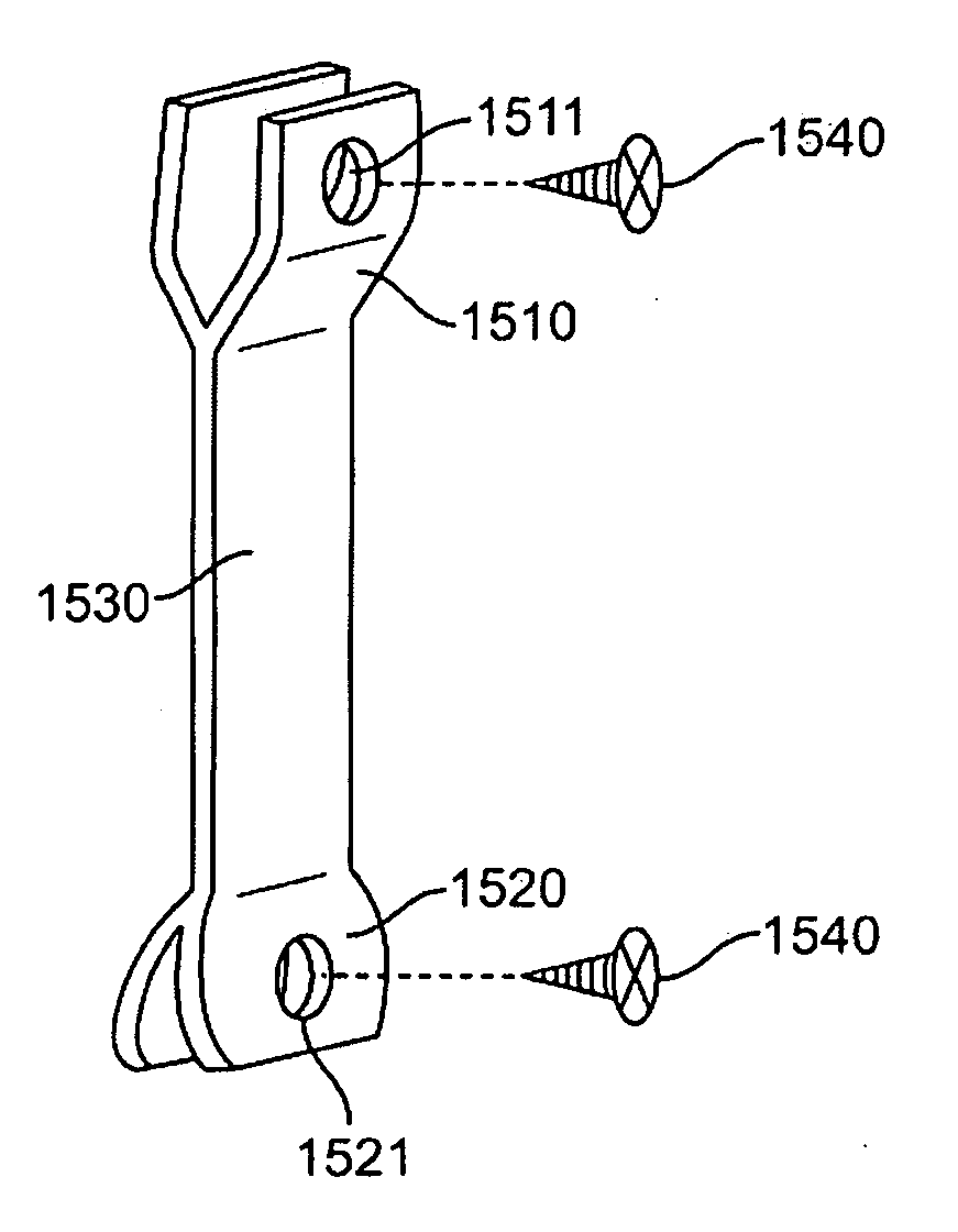
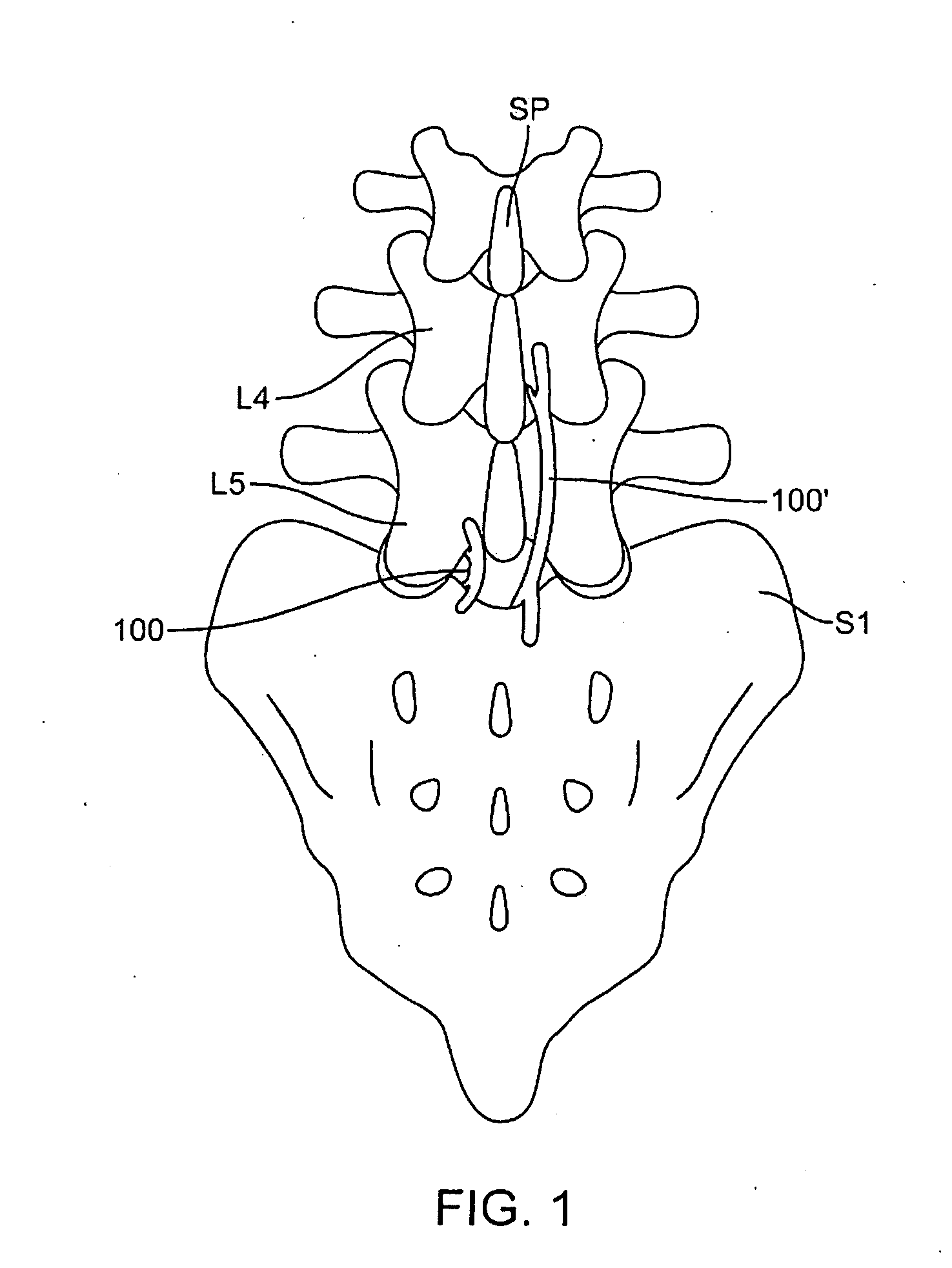
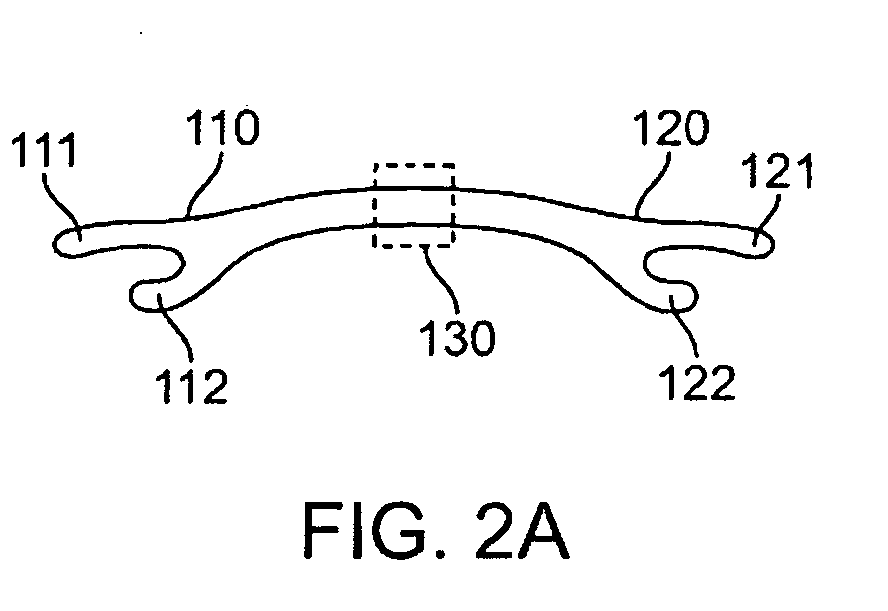
[0049]The present invention is a prosthetic device for distracting spinal column segments in the lumbar and the lumbar-sacral regions by engaging the spinal column segments. Engagement occurs with two engagement arms that are configured to distract the targeted spinal segments to relieve pain and discomfort associated with spinal stenosis or other spinal disorders. Alth...


PUM


Abstract

Disclosed is a prosthetic device for distracting spinal column segments in the lumbar and the lumbar-sacral regions comprising a first engagement arm, a second engagement arm, a coupling mechanism and a locking mechanism. The first and the second engagement arms are configured to receive a lamina portion of the spinal column segment. The coupling mechanism is disposed between the first and the second engagement arms and is configured to allow the device to transition from an unextended configuration to an extended configuration in order to distract the spinal column segment. The locking mechanism is configured to maintain the extended configuration of the device.

Description

CROSS-REFERENCES TO RELATED APPLICATIONS[0001]This application claims priority to provisional applications 61 / 131,427 filed on Jun. 9, 2008; 61 / 132,978 filed on Jun. 23, 2008; 61 / 135,161 filed on Jul. 17, 2008; and 61 / 201,657 filed on Dec. 15, 2008.BACKGROUND OF THE INVENTION[0002]1. Field of the Invention[0003]This invention relates generally to spinal prosthetic devices and more specifically to apparatus and approaches for interlaminar process, interspinous process, and spinolaminar junction distraction and stabilization for treatment of spinal stenosis.[0004]2. Description of the Related Art[0005]The spine and its components can become damaged through disease, injury, or natural degeneration. In such cases, the vertebrae no longer articulate or properly align with each other. This can result in deviation from the normal spinal structure, loss of mobility, and pain or discomfort. For example, degenerative phenomena such as spinal stenosis, spondylosis, spondylolisthesis, or osteoa...

Claims


Application Information

Patent Timeline
Patent Type & Authority Applications(United States)
IPC IPC(8): A61B17/70A61B17/88
CPCA61B17/7055A61B17/7071A61B17/7065A61B17/7062
Inventor BERTA, SCOTT COLLINSVANINETTI, MICHAEL ANTHONYLAD, SHIVANAND
Owner SPRINGBACK
Why Eureka
Try Eureka