Percutaneous transvalvular intrannular band for mitral valve repair

Inactive Publication Date: 2010-05-13
HEART REPAIR TECH INC
View PDF53 Cites 157 Cited by
  • Summary
  • Abstract
  • Description
  • Claims
  • Application Information

AI Technical Summary

Benefits of technology

[0020]In some embodiments, disclosed herein is a method of delivering a transvalvular intraannular implant. The method includes the steps of providing a delivery catheter, the delivery catheter comprising an elongate body; a movable outer sheath; and a transvalvular intraannular implant having a longitudinal axis and comprising a valve leaflet support portion and an anchoring portion, the valve leaflet support portion at least partially longitudinally offset from the anchoring portion; percutaneously delivering the delivery catheter to the vicinity of a heart valve annulus; transforming the implant from a first radially reduced configuration to a second radially enlarged configuration; and positioning the implant in its second radially enlarged configuration within the heart valve annulus such that the implant is oriented in the valve annulus such that the longitudinal axis of the implant is oriented substantially transversely to a coaptive edge of a heart valve positioned within the valve annulus. The heart valve annulus can be, for example, a mitral, aortic, tricuspid, or pulmonary valve annulus. In some embodiments, transforming the implant from the first radially reduced configuration to the second radially enlarged configuration comprises retracting or pushing forward the movable outer sheath of the delivery catheter, exposing the implant. The delivery catheter can further include a self-expandable support structure, such as a ring or stent for example, operably connected to the transvalvular implant. Percutaneously delivering the delivery catheter to the vicinity of the valve annulus can include one or more of approaching the valve annulus from a supraannular location, infraannular location, cardiac septum, such as the intra-atrial or intra-ventricular septum, a vascular cut-down, or a thoracoscopic procedure. The anchoring portion of the implant can be secured to tissue of the valve annulus, such as passing a

Problems solved by technology

Various disease processes can impair the proper functioning of one or more of these valves.
In addition, damage to the ventricle from prior heart attacks (i.e., myocardial infarction secondary to coronary artery disease) or other heart diseases (e.g., cardiomyopathy) can distort the valve's geometry causing it to dysfunction.
The predominant cause of dysfunction of the mitral valve is regurgitation which produces an ineffective cardiac pump function resulting in several deleterious conditions such as ventricular and atrial enlargement, pulmonary hypertension and heart-failure and ultimately death.
Historically, the surgical approach to patients with functional mitral regurgitation was mitral valve replacement, howev

Method used


Image

  • Percutaneous transvalvular intrannular band for mitral valve repair
  • Percutaneous transvalvular intrannular band for mitral valve repair
  • Percutaneous transvalvular intrannular band for mitral valve repair

Examples


Embodiment Construction

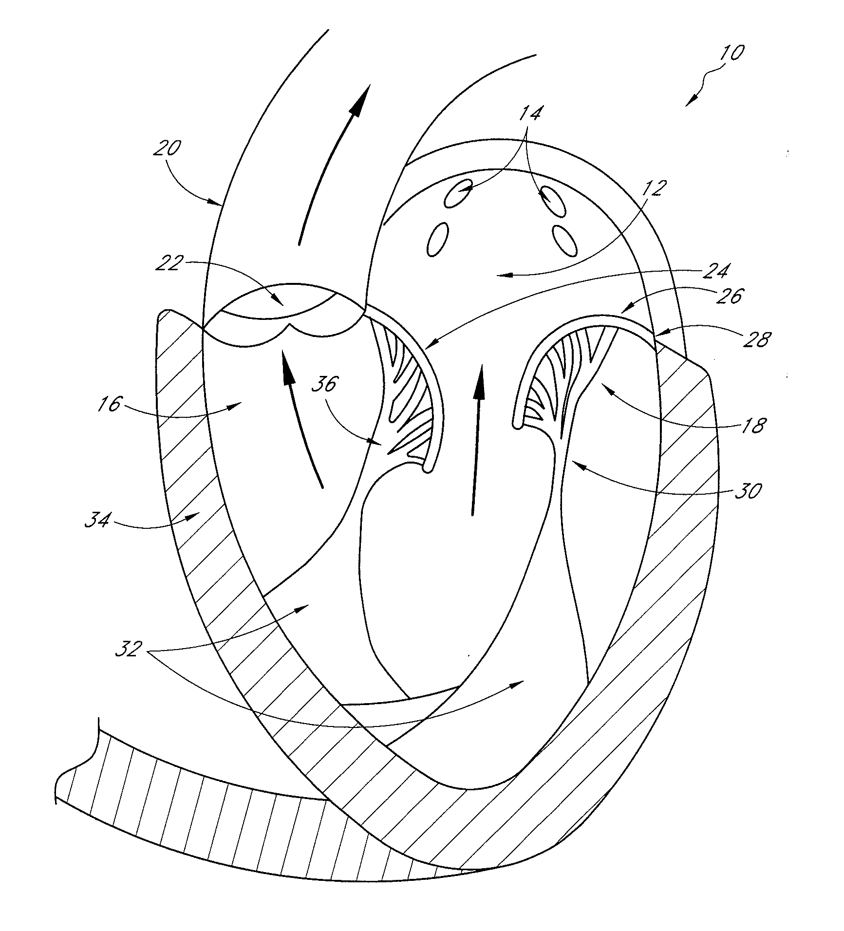
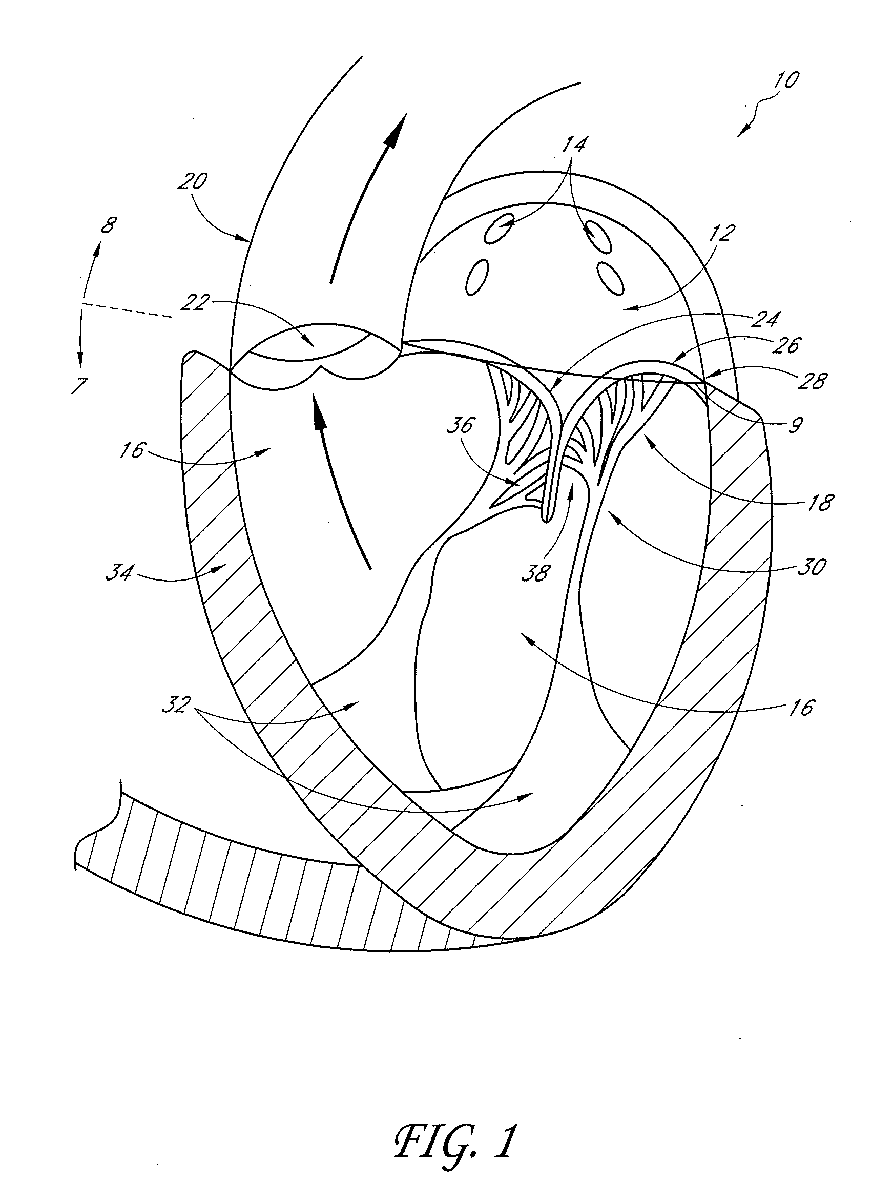
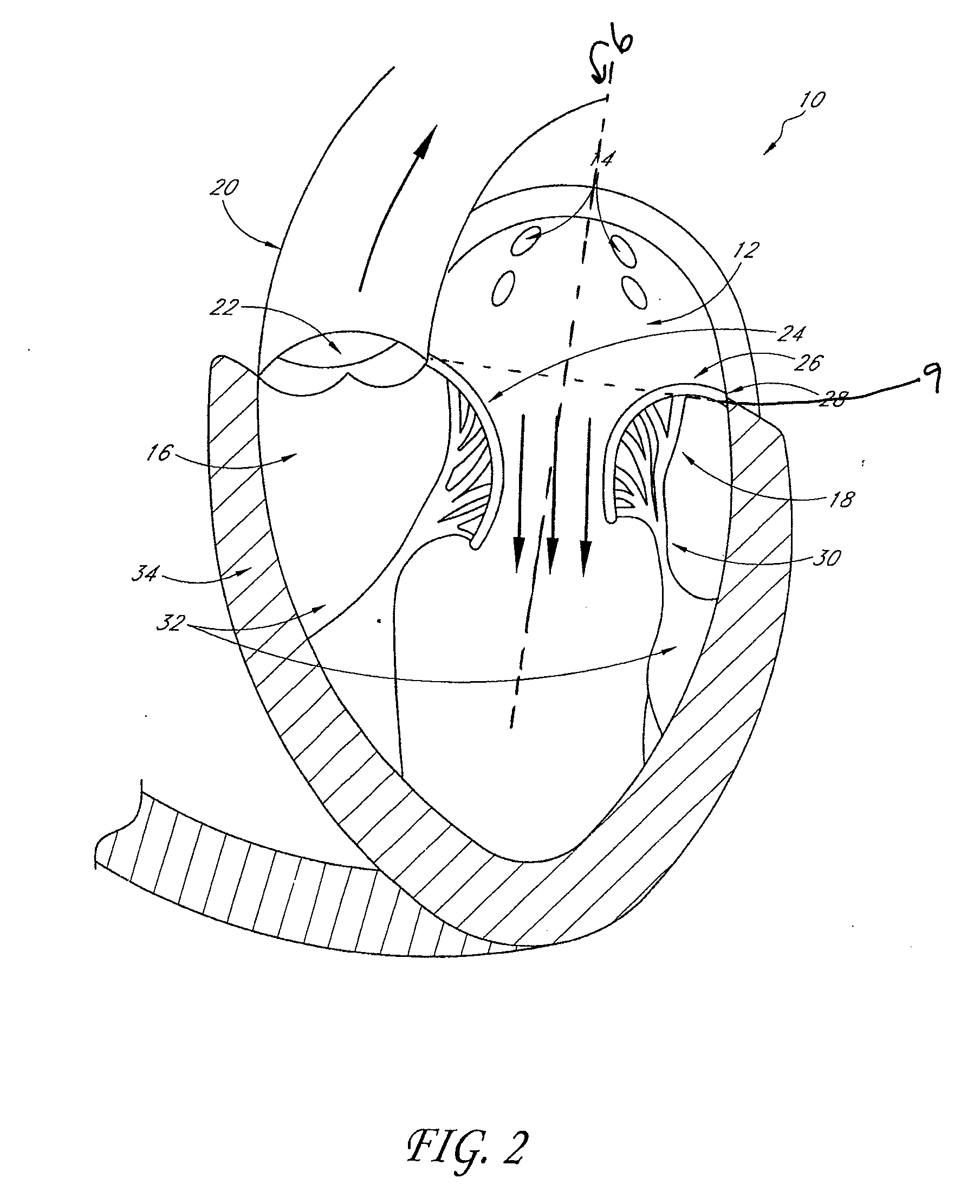
[0100]FIG. 1 illustrates a cross-sectional view of the heart 10 with a normal mitral valve 18 in systole. As illustrated, the heart 10 comprises the left atrium 12 which receives oxygenated blood from the pulmonary veins 14 and the left ventricle 16 which receives blood from the left atrium 12. The mitral valve 18 is located between the left atrium 12 and left ventricle 16 and functions to regulate the flow of blood from the left atrium 12 to the left ventricle 16. During ventricular diastole, the mitral valve 18 is open which allows blood to fill the left ventricle 16. During ventricular systole, the left ventricle 16 contracts, which results in an increase in pressure inside the left ventricle 16. The mitral valve 18 closes when the pressure inside the left ventricle 16 increases above the pressure within the left atrium 12. The pressure within the left ventricle 16 continues increasing until the pressure within the left ventricle 16 exceeds the pressure within the aorta 20, which...


PUM


Abstract

Mitral valve prolapse and mitral regurgitation can be treating by implanting in the mitral annulus a transvalvular intraannular band. The band has a first end, a first anchoring portion located proximate the first end, a second end, a second anchoring portion located proximate the second end, and a central portion. The central portion is positioned so that it extends transversely across a coaptive edge formed by the closure of the mitral valve leaflets. The band may be implanted via translumenal access or via thoracotomy.

Description

CROSS-REFERENCE TO RELATED APPLICATIONS[0001]This application is a continuation-in-part of U.S. patent application Ser. No. 12 / 104,011 filed Apr. 16, 2008, the disclosure of which is incorporated by reference herein in its entirety.BACKGROUND OF THE INVENTION[0002]1. Field of the Invention[0003]Embodiments of the present invention relate generally to treatment of mitral or tricuspid valve prolapse and mitral regurgitation, and more specifically, relate to the use of a transvalvular intraannular band to treat mitral valve prolapse and mitral regurgitation.[0004]2. Description of the Related Art[0005]The heart is a double (left and right side), self-adjusting muscular pump, the parts of which work in unison to propel blood to all parts of the body. The right side of the heart receives poorly oxygenated (“venous”) blood from the body from the superior vena cava and inferior vena cava and pumps it through the pulmonary artery to the lungs for oxygenation. The left side receives well-oxy...

Claims


Application Information

Patent Timeline
IPC IPC(8): A61F2/24
CPCA61F2/2445A61F2/2427A61F2/2457A61F2/2454A61F2/2436
Inventor SUBRAMANIAN, VALAVANUR A.AFZAL, THOMASHULME, GARYCHRISTIAN, JEFFREYREO, MICHAEL L.
Owner HEART REPAIR TECH INC
Why Eureka
Try Eureka