
Automated self-storage system

a self-storage system and automatic technology, applied in the field of automatic self-storage facilities, can solve the problems of consuming a large amount of storage facility space, consuming a significant amount of space, and occupying a large amount of real esta

Inactive Publication Date: 2010-05-13
TALLEY PAUL A +1
View PDF12 Cites 58 Cited by
  • Summary
  • Abstract
  • Description
  • Claims
  • Application Information

AI Technical Summary

Benefits of technology

"The present invention is a system for automated self storage that allows users to easily access and retrieve their storage units without having to enter the facility or navigate through internal corridors and staircases. The system includes a central control system that maintains records of which container each user's storage unit is stored in, and the user's access information. The system also includes a key pad or other electronic interface device at the facility access point for user authentication. The system allows for efficient use of space, reduces facility costs, and increases land usage density. The storage units can be of different sizes and can be accessed from multiple sides. The system also allows for easy management of the retrieval and return of storage units. Overall, the system provides a convenient and efficient solution for public access self storage."

Problems solved by technology

Limited users access to the facility is provided at predesignated locations.
Because of the need to access each minute individually, a large portion of the facility is consumed by access passageways.
This again consumes significant amounts of storage facility space.
If each of the units must face the exterior of the facility, the facility is often a minute to a single level and therefore takes a significant real estate and requires CD of an additional access roads through and around the facility.
Often facilities of this type are there for the series of separate single story buildings and are limited and location because of the need for a large tract of land.

Method used


Image

  • Automated self-storage system
  • Automated self-storage system
  • Automated self-storage system

Examples


Embodiment Construction

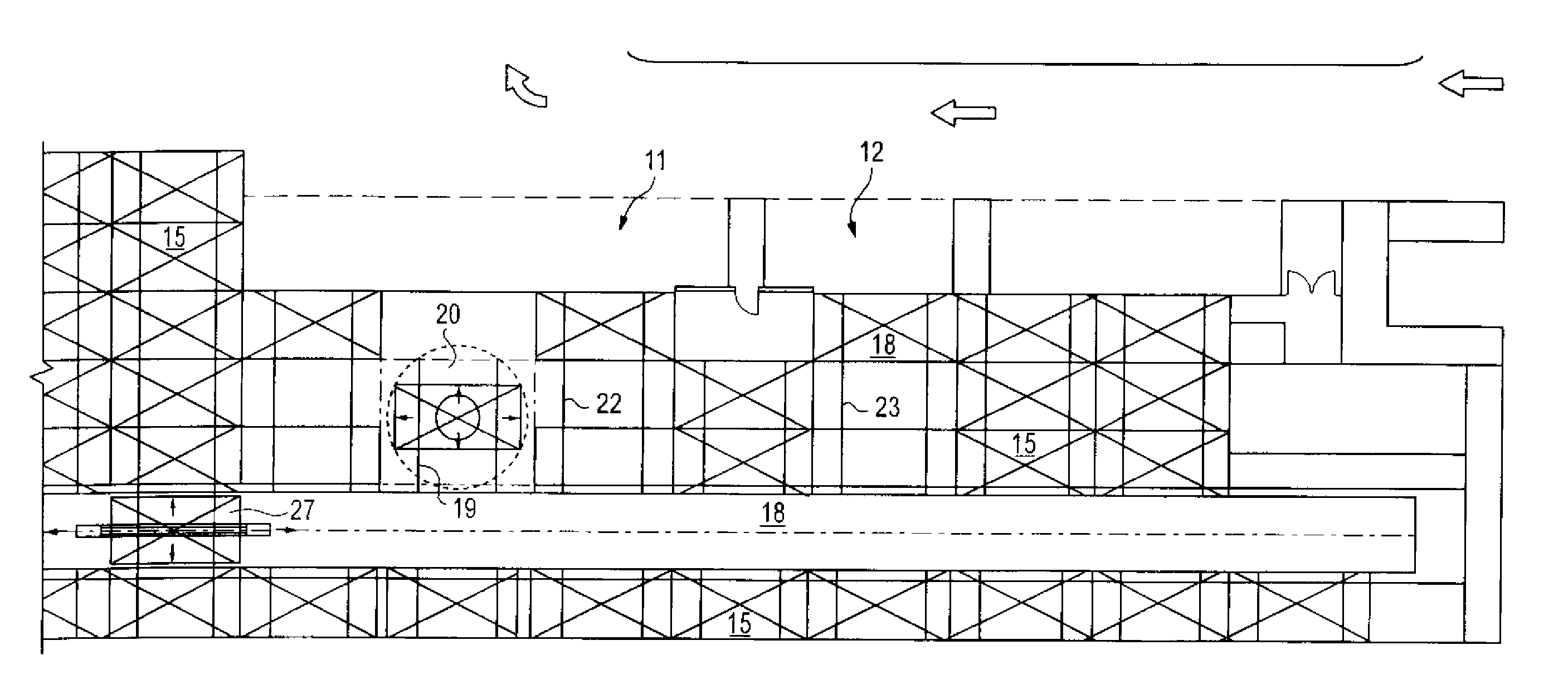
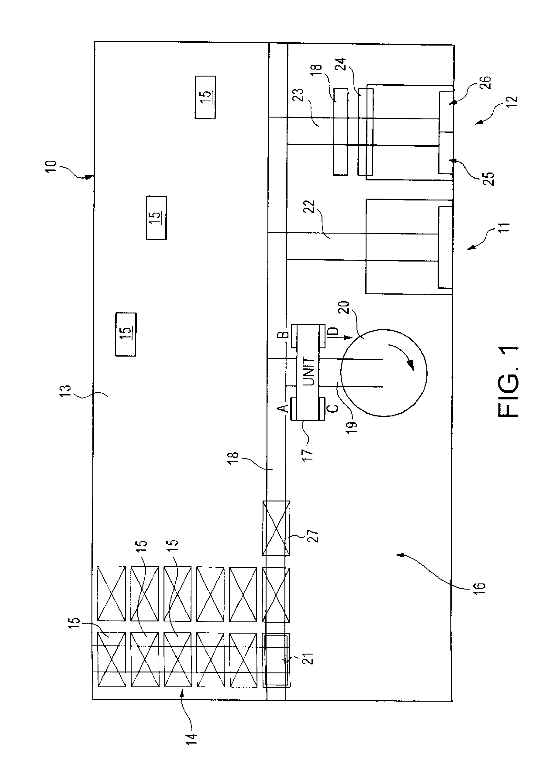
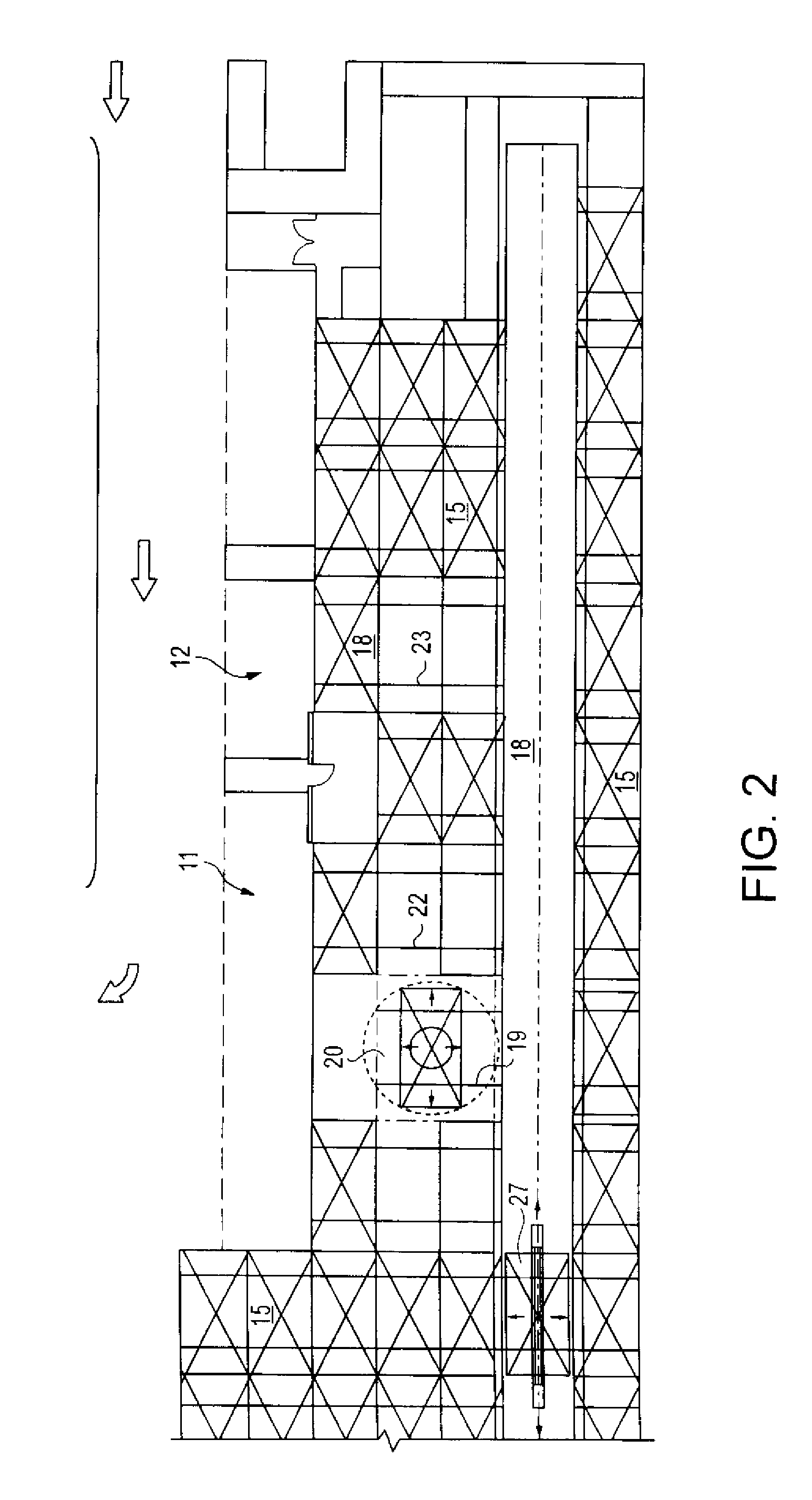
[0033]As illustrated in FIGS. 1 and 2, the overall facility 10 as shown from above in a block floor plan view, includes for example to access ports 11 and 12 at the front of the facility and storage area 13 at the rear of the facility. Exemplary storage locations 14 are shown at the left side of FIG. 1. Illustrated in rear storage locations are additional storage units 15. Units 15 can be stored throughout the facility in similar rows as those illustrated in area 14. Not all locations for storage units are illustrated but are understood. The left side of the front of the facility 16 can also be used for storage or for additional access areas such as areas 11 and 12.

[0034]In the exemplary layout illustrated in FIG. 1 and / or FIG. 2, storage unit 17 is shown being moved by the facility system. Storage unit 17 has been moved from main railway 18 to the rotation unit railway 19 so that the unit can be moved onto rotating platform 20 to change the orientation of unit 17 if desired. As ill...


PUM


Abstract

An automated self storage facility which stores individual items in movable storage units and / or storage containers which are stored throughout the storage facility. Limited users access to the facility is provided at predesignated locations. The users container is transported between its storage location and the access location by the automated robotic system within the facility to provide efficient handling, storage and retrieval of goods in a storage facility. A central control system maintains a record container location throughout the facility. Upon request the system retrieves a container and delivers it. The containers may be partitioned such that a single container may have multiple compartments. In this case the automated system maintains a record of compartments and appropriately orients the container at the access location upon retrieval.

Description

RELATED APPLICATIONS[0001]This application is a continuation of U.S. application Ser. No. 11 / 512,401, filed Aug. 30, 2006, entitled Automated Self-Storage System; which application claims benefit of priority of U.S. Provisional Application No. 60 / 712,679, filed Aug. 30, 2005. The above-identified related applications are incorporated herein by reference.BACKGROUND OF THE INVENTION[0002]The present invention relates to an automated self storage facility which stores individual items in movable storage units and / or storage containers which are stored throughout the storage facility. Limited users access to the facility is provided at predesignated locations. The users container is transported by the system within the facility to the access location when accessed by the user. The system of the present invention provides efficient handling, storage and retrieval of goods in a storage facility.[0003]In a typical self storage facility, each storage unit is provided with its own access doo...

Claims


Application Information

Patent Timeline
Patent Type & Authority Applications(United States)
IPC IPC(8): B65G1/137G06F7/00
CPCB65G1/0407
Inventor TALLEY, PAUL A.PUGLIESE, III, ANTHONY V.
Owner TALLEY PAUL A
Learn More