Eureka AIR delivers breakthrough ideas for toughest innovation challenges, trusted by R&D personnel around the world.

System and method for adjustable repair and reinforcement of non-standard doors and jambs

a door and jamb technology, applied in the field of adjustable door security system, can solve the problems of general visibility of system components, and achieve the effects of enhancing structural integrity, enhancing strength, and enhancing structural integrity of entry door assembly

Inactive Publication Date: 2010-05-20
ARMOR CONCEPTS
View PDF41 Cites 4 Cited by
  • Summary
  • Abstract
  • Description
  • Claims
  • Application Information

AI Technical Summary

Benefits of technology

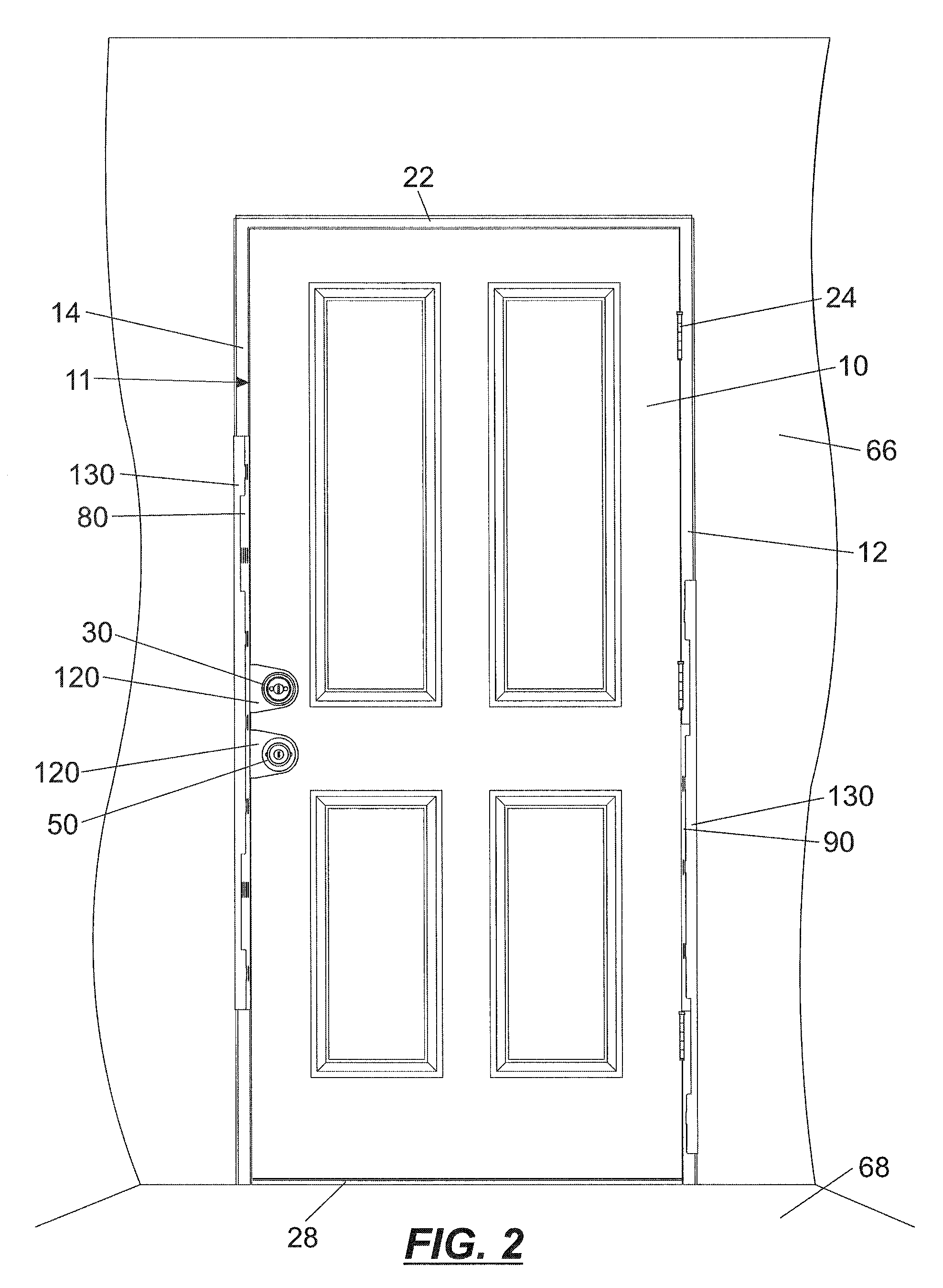
[0018]It is an object of the present invention to overcome the foregoing drawbacks and shortcomings of the current state of art with door security assemblies that focus on the overall structural inadequacy of doors mounted in and supported by wooden door jambs. The components of the present system can be used alone or in combination to equally and complimentarily address the conventional points of forced entry and structural vulnerability of vertically hung hinged doors with non-standard assemblies, for new and existing structures by utilizing adjustable wrapping technology. Component parts of the system are generally obscured from view by design. The present invention affords greater strength, stability, and adjustable support to vertically hung hinged door assemblies that have not been heretofore achieved, in such a maimer. As well the object of the present invention is to provide a structurally sound means of repair for previously damaged said door assemblies. After installation, the component parts alone or in combination cooperate to substantially benefit and enhance the structural integrity of entry door assembly.
[0020]The door security system presented here will serve to substantially improve the strength and reliability of the entire door assembly. This system will typically comprise up to four to six main components all suitably manufactured of rugged material, preferably steel, and all necessary securing hardware. Securing hardware will depend upon the door application and will be sized to pass through the doorjamb immediately surrounding the door and penetrate a sufficient depth into the rough frame of the main structure. This system can be incorporated into the manufacturing process of door assemblies, applied cooperatively to new assemblies, or installed on previously hung doors assemblies as functions of the overall system benefit. The latter application can be done by the average layperson with basic hand tools and minimal carpentry experience. Thus significant features of the present invention include allowing for application of the system on previously installed door assemblies and the repairing of damaged assemblies while originally placed, in simple and uncomplicated fashion. The lack of complexity is achieved by the thin three-sided wrapping construction of the components, which allows them to easily slide onto position in the applicable areas.
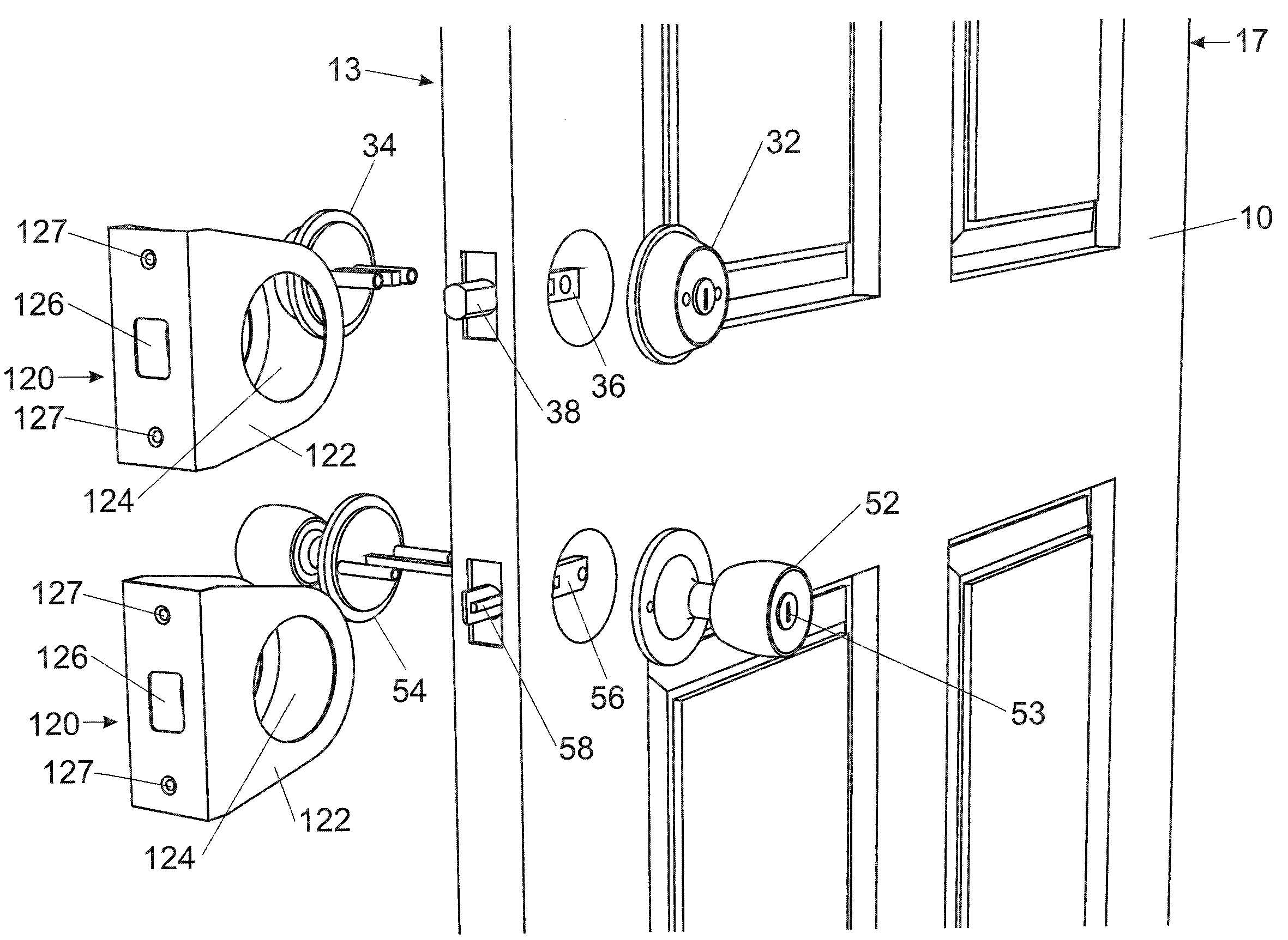
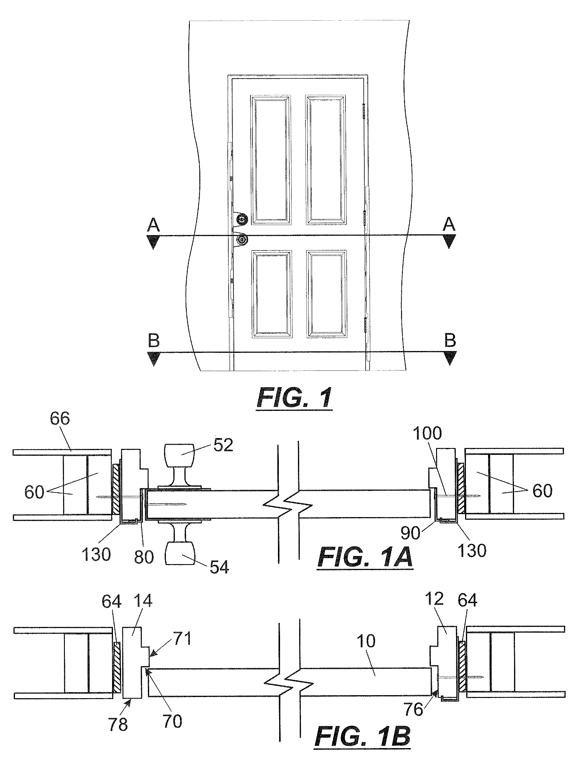
[0023]1. The door jamb shielding component corresponding to the door slab free swinging edge and coinciding doorjamb comprise two elongated, substantially equal length members, each having basically “L” shaped cross sections and constructed of about 16-24 gauge steel sheet metal. The two members fit together to form a slide-on sleeve. The sleeve serves to wrap around the door jamb from the facing (i.e., medial) surface of the door jamb adjacent the free swinging edge of the door slab, around to the interior edge of the door jamb (the sleeve is adjustable to accommodate door jambs of varying thicknesses), and finally extending along the backside (i.e., lateral surface) of the door jamb from the interior to the exterior edge. The sleeve mounts with the common adjustable center section of the sleeve positioned to flushly contact and engage the interior edge of the doorjamb; while the side panels extend in parallel, flushly contacting the door jamb on both sides, towards the exterior edge. In the region of the free-swinging edge of the door slab and bolt receiving holes of the doorjamb, there will be holes in the sleeve to accommodate upper and lower lock bolts. Typically this door assembly arrangement comprises a dead bolt lock oriented above a latch bolt lock. The suitably sized dead bolt lock when manipulated will pass through a first side panel of the sleeve and proceed through the original wooden doorjamb. The length of the jamb shield and its the wrapping feature serve to spread any force applied to the doorjamb while transferring such load to the door assembly surrounding structure, thereby preventing the splitting of the door jamb. After installation of the doorjamb component, on a typical door assembly, only a relatively small portion of the jamb member is left exposed above and below the device. Notably this limits the force applied to the doorjamb in the unprotected areas and ensures that this force will be a shear-type force. These shear forces are applied to the entire cross section of the doorjamb in this region instead of the minimal strike plate area of the doorjamb in an unprotected door assembly. This wrapping feature of the sleeve is a major factor in the uniqueness of this component and the present system of invention. The technology allows the doorjamb to be wrapped and, once secured with screws, the rigidity of the jamb is significantly increased. Furthermore the jamb-shielding component allows for universal application by accommodating various lock spacing between the previously mentioned traditional locking mechanisms. The doorjamb shield has considerations for new manufactured door assemblies and may be incorporated into the doorjamb prior to application of the door assembly weather seal at the factory.
[0025]3. The door-shielding component is an elongated section of about 16-24 gauge steel sheet metal that has a generally U-shaped cross section. The door-shielding component serves to wrap around the free-swinging edge of the door slab in the region corresponding to the lock bolts exiting the door. The door-shielding component mounts with the bottom of the “U” flushly contacting the free swinging edge of the door slab and the elongated side panels extending in parallel, flushly contacting the door on both sides, along the interior and exterior faces of the door slab, towards the hinge side of the door. There is an opening in the bottom of the “U” positioned to allow the lock bolt mechanisms to operate without interference. The bolts of the upper and lower locks, when manipulated accordingly, will pass through the door shield component and into the facing surface of the jamb shield component before continuing as detailed in the jamb component description. Another hole with coinciding orientation to the hole in the bottom of the “U” will pass through door shield component perpendicular to the aforementioned holes. These holes will serve as the lock mounting space. The primary function of the door shield component as applied to the present invention is to prevent force on the lock bolts from splitting the free-swinging edge of the door slab. The door-shielding component subsequently serves to prevent tampering with the locking mechanism. Finally this component can be effective in preventing foreign objects from being forced between the door slab free swing edge and the door jamb interface by creating a much closer tolerance in this region. There are at least two versions of this component. A standard version allows for typical lock spacing between the dead bolt and latch bolt. Furthermore a universal application accommodates various lock spacing between the previously mentioned traditional locking mechanisms. The door-shielding component may have considerations for new manufactured door assemblies and may be incorporated into the frame prior to installation of the door assembly weather seal at the factory.

Problems solved by technology

Component parts of the system are generally obscured from view by design.

Method used


Image

  • System and method for adjustable repair and reinforcement of non-standard doors and jambs
  • System and method for adjustable repair and reinforcement of non-standard doors and jambs
  • System and method for adjustable repair and reinforcement of non-standard doors and jambs

Examples


Embodiment Construction

[0043]The present invention now will be described more fully hereinafter with reference to the accompanying drawings, in which embodiments of the invention are shown. This invention may, however, be embodied in many different forms and should not be construed as limited to the embodiments set forth herein; rather, these embodiments are provided so that this disclosure will be thorough and complete, and will fully convey the scope of the invention to those skilled in the art. Like numbers refer to like elements throughout.

[0044]The present invention described and further detailed herein is particularly useful as a security device for the reinforcement of new door assemblies and, because of the ability to be adjustable, is equally suited for the repair of entry door assemblies with non-standard dimensions, while the door assembly remains in place. In place refers to the door assembly as mounted in an existing structure with means having been taken to ensure fixation to the structure i...


PUM


Abstract

A door security system serves to substantially improve the reliability of the entire door assemblies with non-standard doorjamb thicknesses. The system may comprise up to four or more components. An adjustable doorjamb shield may be mounted around a doorjamb on the side of the doorjamb corresponding to the door slab free swinging edge. Another adjustable doorjamb shield may also be mounted on a doorjamb on the hinge side of the door jamb. The adjustable shields comprise attachable sleeves that wrap on three sides around the door jamb to reinforce and stabilize the door system.

Description

FIELD OF THE INVENTION[0001]The present invention relates to an adjustable door security system, specifically to a mounting system for reinforcement, repair and improved security of non-standard door assemblies including but not limited to those with sidelights, wooden enclosures and non-standard jamb member thicknesses.BACKGROUND OF THE INVENTION[0002]There is an ever increasing need and demand for improving the security and structural integrity of entry doors. This demand is being driven by the repeated occurrences of unauthorized and forced entry through entry doors.[0003]Typically such improvements have focused on pick resistant locks, longer and stronger dead bolts, and guard plates. Generally the strengthening and protecting of the locks and bolts have proven to be ill fated attempts at increasing the security of entry doors. The fact is these locks and bolts are mounted and anchor into very soft wooden door slabs and jambs, making their overall effectiveness minimal for secur...

Claims


Application Information

Patent Timeline
Patent Type & Authority Applications(United States)
IPC IPC(8): E06B1/52
CPCE05B15/0205E06B5/113E05B17/2084E05B15/024Y10T292/79
Inventor YOUNG, GLENN I.
Owner ARMOR CONCEPTS
Why Eureka
Eureka Blog
Learn More