Tank liquid level gauge system

a liquid level gauge and tank technology, applied in the field of tanks, can solve the problems of foul operation of tank liquid level gauges, erroneous readings, and mechanism faking of such gauges

Inactive Publication Date: 2010-05-20
CLANTON SHANE H
View PDF14 Cites 16 Cited by
  • Summary
  • Abstract
  • Description
  • Claims
  • Application Information

AI Technical Summary

Problems solved by technology

However, mechanical gauges are susceptible to freezing rain, which can foul their mechanism and result in erroneous readings.
An additional difficulty is that insects and small birds sometimes find enclosures associated with mechanical gauging means to be a convenient location to build their nests, which frequently foul operation of such gauges.

Method used


Image

  • Tank liquid level gauge system
  • Tank liquid level gauge system
  • Tank liquid level gauge system

Examples


Embodiment Construction

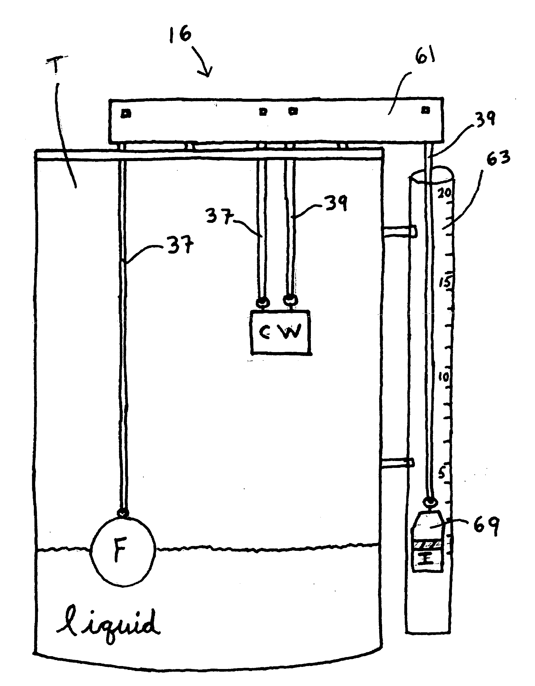
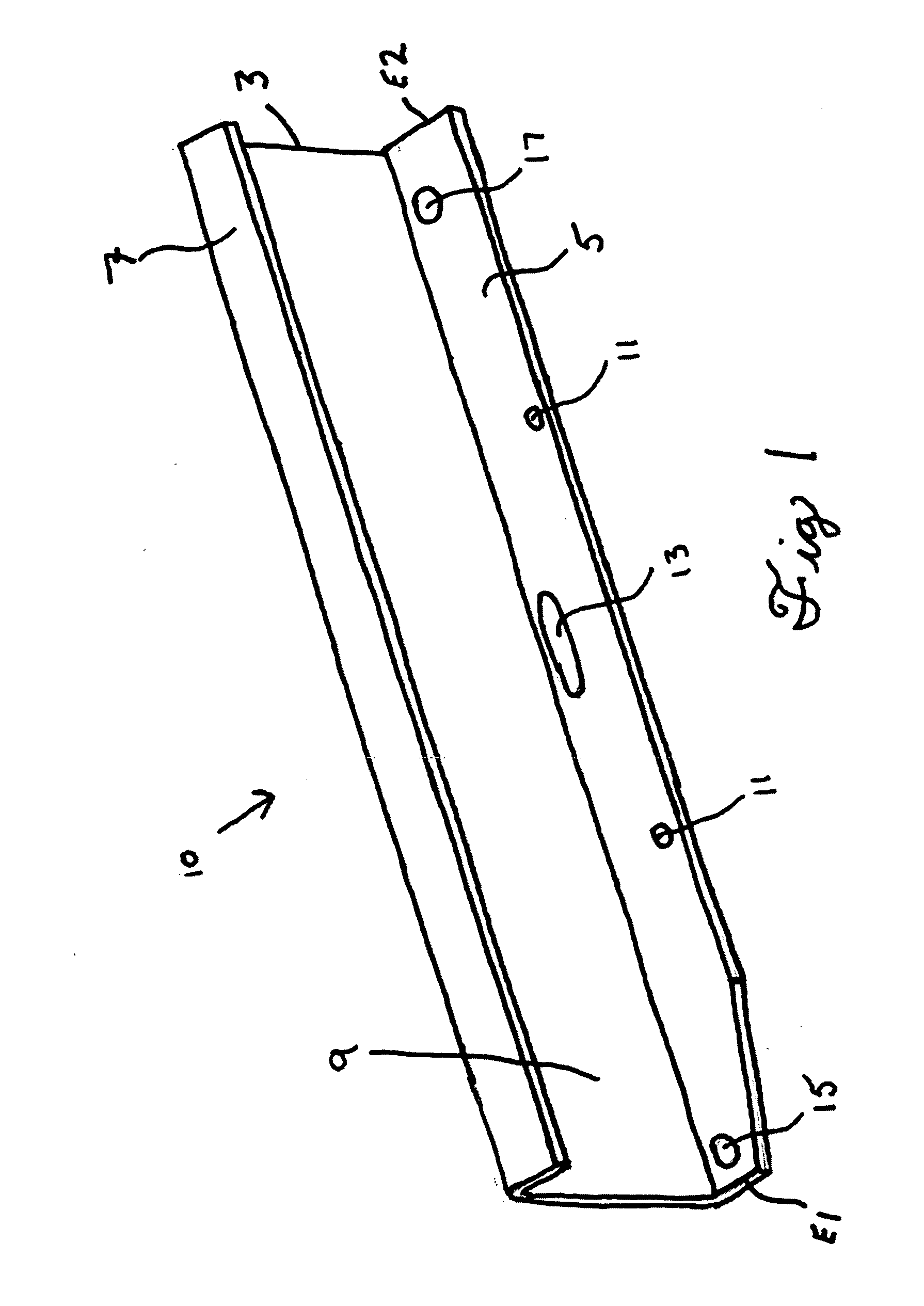
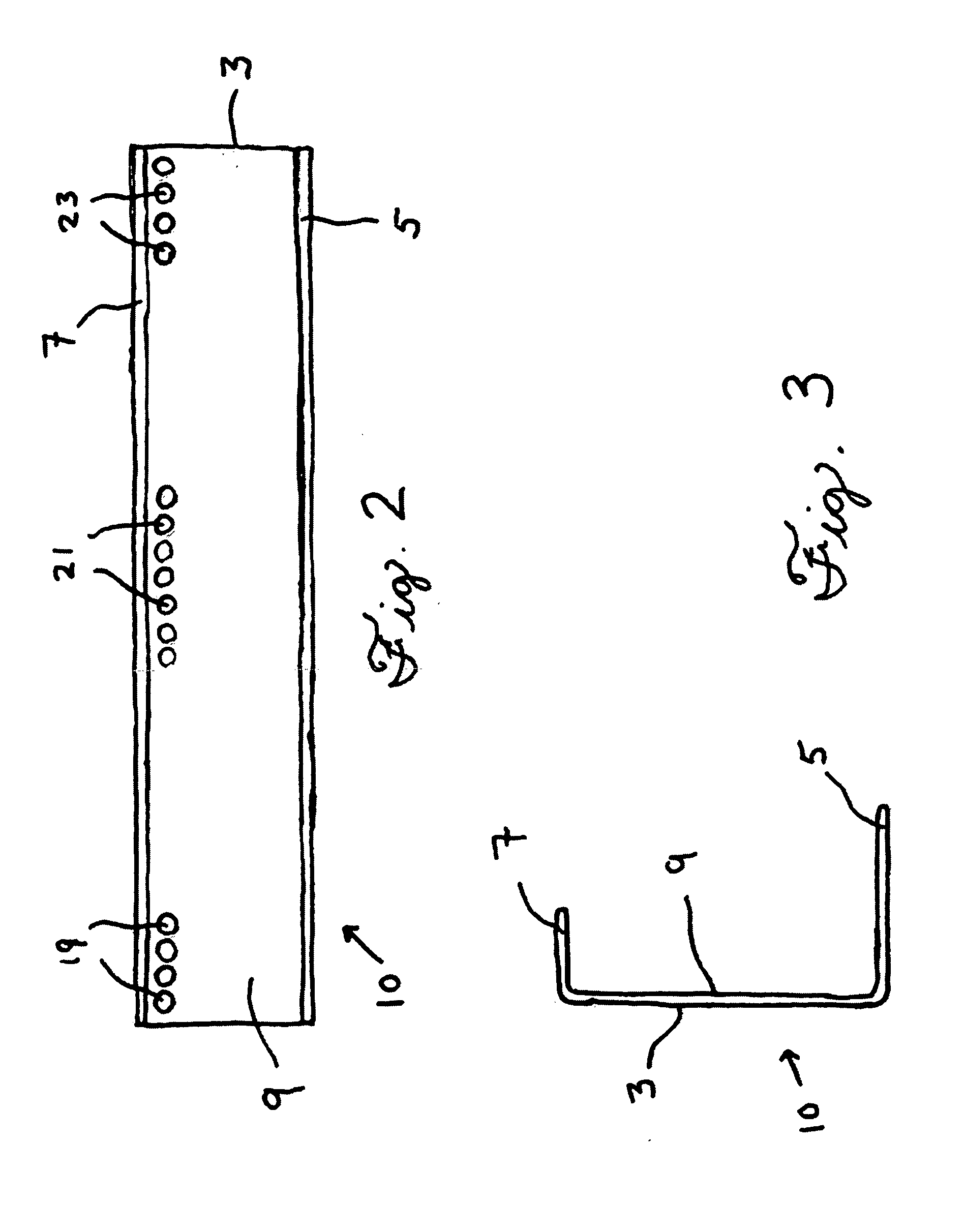
[0019]Referring to the drawings, presented as being illustrative of the invention only and not being delimitive of same, FIG. 1 provides a perspective view of a main frame 10 of a gauge control assembly 16 (FIG. 14) according to an embodiment of the present invention. In this embodiment, the main frame 10 includes a wall 3 having an interior surface 9. There is an upper flange 7 disposed along the upper edge of the wall 3, and a lower flange 5 disposed along the lower edge of the wall 3. The lower flange 5 includes mounting holes 11 disposed through its surface, to enable conventional fasteners including screws, rivets, and bolts to pass through, for affixing the main frame 10 to a selected surface, which includes the top of a tank in which a liquid substance is contained. In this embodiment there is further provided a provision for enabling a cable to pass, which provision comprises slot 13 disposed through the surface of the lower flange 5. In this embodiment there are also holes ...


PUM


Abstract

A fouling-resistant arrangement useful for guiding lengths of cables having functional devices including a float, counterweight, and indicator bob attached at their ends, collectively useful in indicating the liquid level of a storage tank to which a system as herein provided is attached, to a passer-by upon casual glance.

Description

TECHNICAL FIELD[0001]This invention relates generally to tanks in which liquid substances are stored. More particularly, it relates to gauges and apparati capable of being affixed to an external surface of a storage tank, for indicating the level of a liquid substance disposed within the tank.BACKGROUND OF THE INVENTION[0002]Storage tanks in which liquids are to be held until the time of their use or consumption have been in use since the earliest of times. Typically, liquids including water, solvents, hydrocarbons, and oils are commonly contained in liquid storage tanks.[0003]It is generally desirable for a person whose activities concern use of a liquid contained within a storage tank to have a method or means by which the amount of liquid within the tank can be known. One example of a helpful means in this regard is the fuel tank gauge on modern motorized vehicles, such as automobiles and trucks. Another example includes tank farms at petrochemical refineries which often have ele...

Claims


Application Information

Patent Timeline
Patent Type & Authority Applications(United States)
IPC IPC(8): G01F23/58B65D90/48B65D88/02
CPCG01F23/0038G01F23/42
Inventor CLANTON, SHANE H.
Owner CLANTON SHANE H
Why Eureka
Try Eureka