Chipper Knife and Method of Manufacturing a Chipper Knife

Active Publication Date: 2010-05-20
IGGESUND TOOLS
View PDF4 Cites 4 Cited by
  • Summary
  • Abstract
  • Description
  • Claims
  • Application Information

AI Technical Summary

Benefits of technology

[0014]Also the finishing of the thickened cutting edge portions can be carried out in various ways: for instance by grinding using a grinding disc, using a grinding belt, or milling using a milling tool. When using a grinding disc, grinding can be performed by means of the circumferential surface of the disc or by means of a radial surface. In the former case, this means that the thickened cutting edge portion will be slightly concave. In general, finishing should be carried out so that any working stripes of the thickened cutting edge portion will extend at an angle to the cutting edge in order to reduce friction in chipping and prevent fracture-indicating stripes parallel to the cutting edge.
[0015]In a preferred embodiment, the blank is made so that both the thickened cutting edge portion and the edge-forming surface a distance further inward on the chipper knife are flat and parallel to each other. In fact, such a design results in great freedom of forming the thickened cutting edge portion at many different angles in the finishing of the cutting edge portion, while at the same time the consumption of material can be kept at a low level. The thickened cutting edge portion of the blank could, however, also be made with a concave or convex shape, as can also the edge-forming surface further inward on the chipper knife. As mentioned above, the thickened cutting edge portion can, in the finishing operation, also be made with a slightly concave shape. This may be advantageous on the chip side since the chips will have a softer transition before hitting the rest of the edge-forming surface and by reduced wear since the chips are guided away from the holder of the chipper knife and the rotating tool. Summing up, this means that a chipper knife according to the invention in a final embodiment will have a thickened cutting edge portion which makes an angle to, or has a centre of curvature different from, the rest of the edge-forming surface.

Problems solved by technology

This results in high costs of manufacture and stock-keeping of the chipper knives.

Method used


Image

  • Chipper Knife and Method of Manufacturing a Chipper Knife
  • Chipper Knife and Method of Manufacturing a Chipper Knife
  • Chipper Knife and Method of Manufacturing a Chipper Knife

Examples


Embodiment Construction

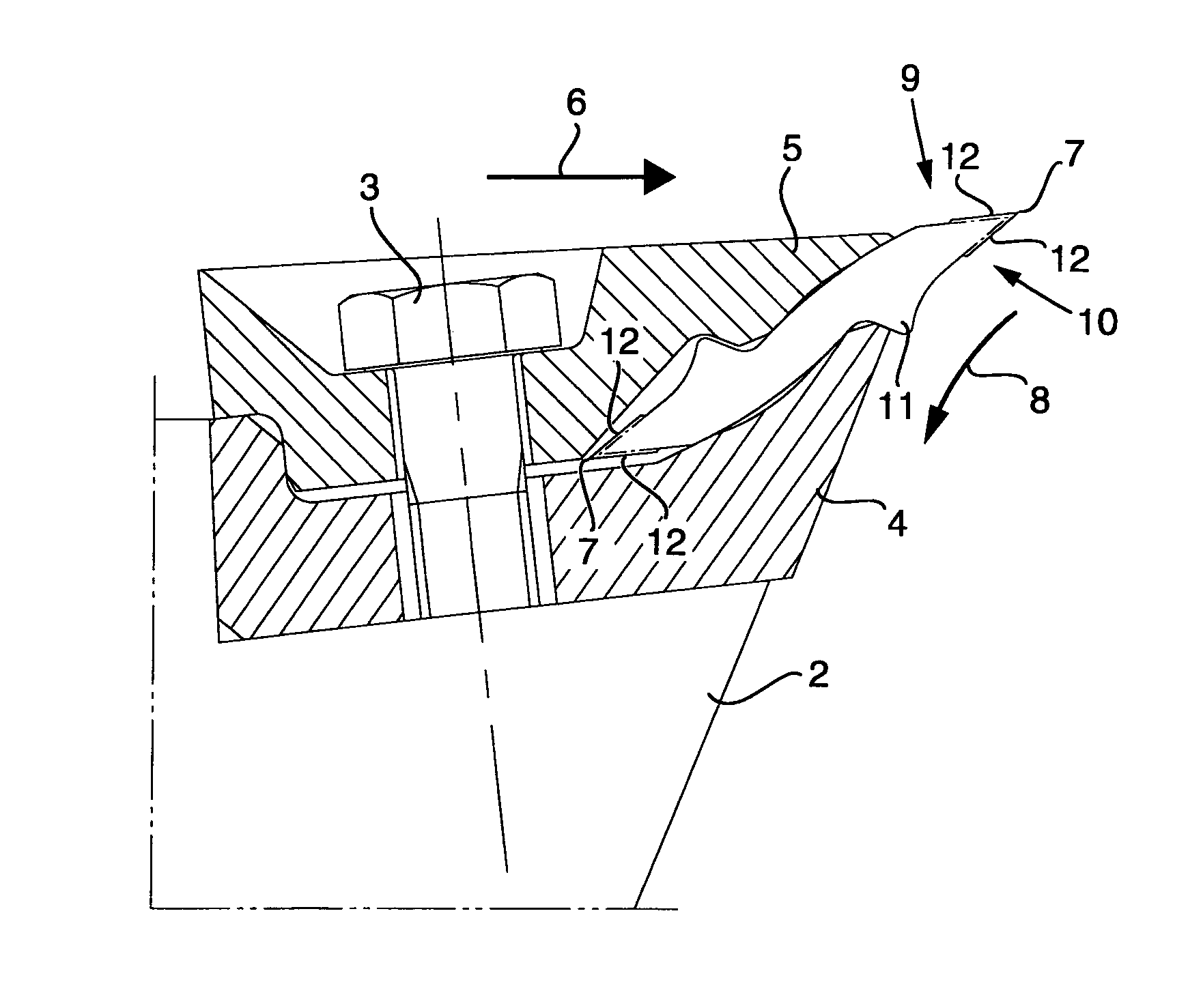
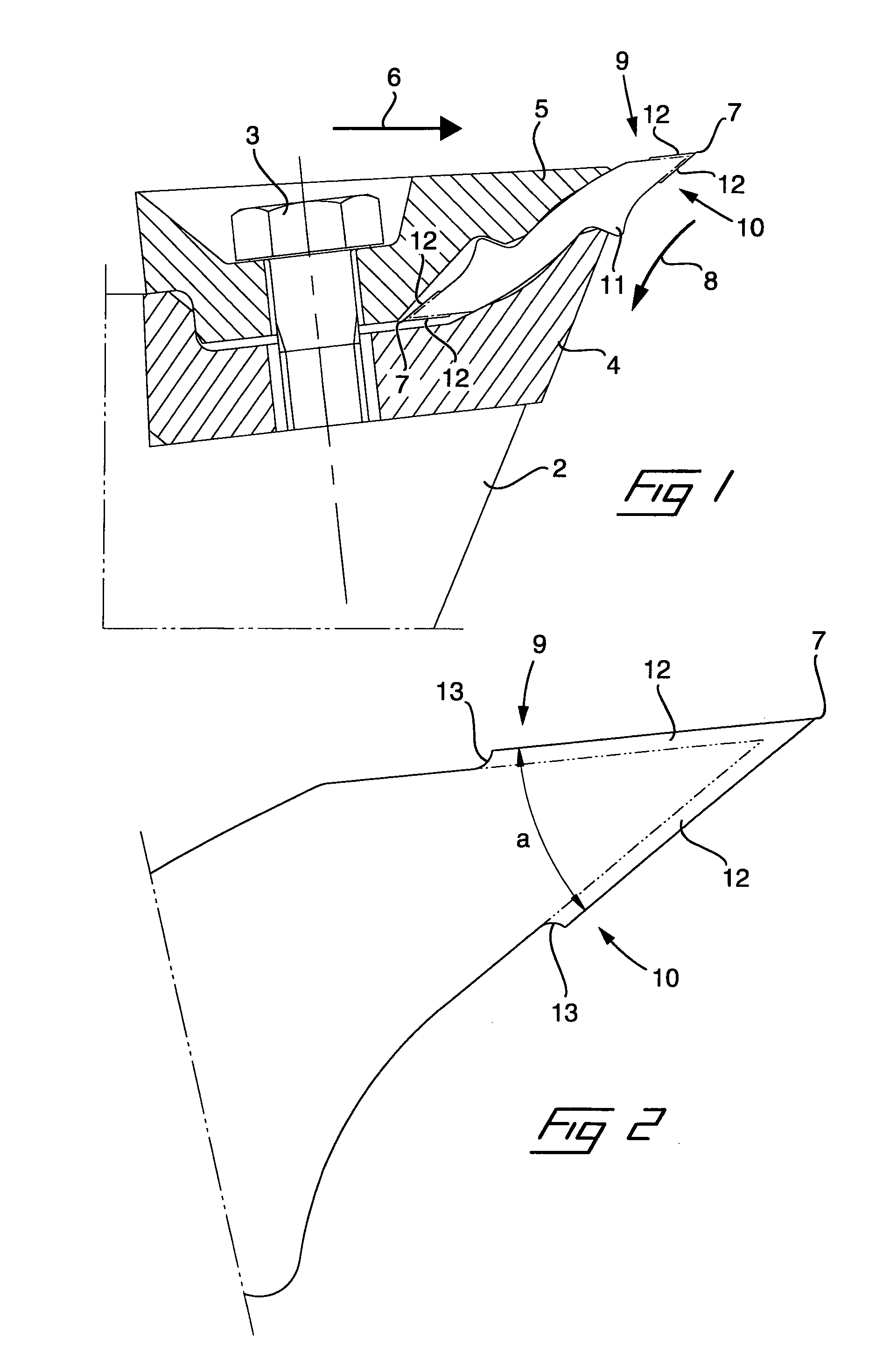
[0023]FIG. 1 illustrates an example of a chipper knife 1 for disintegrating chipping of wood raw material into chips. The shown chipper knife is mounted on a rotating chipper disc 2 and is secured to this by clamping by means of a bolt 3 between an inner and an outer holding part 4 and 5 respectively. The chipper disc 2 is substantially circular and rotates in the figure to the right in the plane of the sheet of paper, that is in the direction of the arrow 6. The chipper disc comprises in a conventional way a number of almost radial through slots, adjacent to the rear edges, seen in the direction of rotation, of which a plurality of chipper knives are mounted in such a manner that cutting edges 7 of the same project over the slot opening. During rotation of the chipper disc 2 and simultaneous feeding of pieces of wood from above in the plane of the sheet of paper, the chipper knives will disintegrate the pieces of wood into chips which are fed in the direction of the arrow 8 through...


PUM

PropertyMeasurementUnit
Lengthaaaaaaaaaa
Lengthaaaaaaaaaa
Lengthaaaaaaaaaa

Abstract

The invention relates to a chipper knife of the type that is adapted to be mounted in chippers which have a rotatable tool, in the form of a disc, drum or frustoconical member, on which are mounted a plurality of such chipper knives to provide, during rotation of the tool and simultaneous feeding of pieces of wood to the same, material-cutting working or disintegrating of the pieces of wood into chips. The chipper knife comprises at least one cutting edge (7) which is defined between two edge-forming surfaces (9, 10) at an acute angle to each other. At least one of the two edgeforming surfaces is formed with a thickened cutting edge portion (12) in the area next to the cutting edge, said thickened cutting edge portion having a shoulder edge (13) toward the rest of the edge-forming surface and forming an angle to, or having a different centre of curvature to, the rest of the edgeforming surface. The invention also relates to a method of manufacturing such a chipper knife.

Description

[0001]The present invention relates to a chipper knife of the type that is adapted to be mounted in chippers which have a rotatable tool, in the form of a disc, drum or frustoconical member, on which are mounted a plurality of such chipper knives to provide, during rotation of the tool and simultaneous feeding of pieces of wood or timber to the same, material-cutting working or disintegrating of the pieces of wood into chips, comprising at least one cutting edge which is defined between two edge-forming surfaces at an acute angle to each other.[0002]The invention also relates to a method of manufacturing such a chipper knife.BACKGROUND ART[0003]In the production of chips from wood raw material, chippers of the above described type are used. Such chippers can be of the type that is used in order to chip, from the entire wood raw material, chips for production of paper pulp or production of boards, but can also be “reducers” which are used for forming blocks of round logs and which ha...

Claims


Application Information

Patent Timeline
IPC IPC(8): B27L11/00B21K5/12B23P6/00
CPCY10T29/49748B27L11/005
Inventor ENGNELL, MATS
Owner IGGESUND TOOLS
Why Eureka
Try Eureka