Rfid-based corrosion and moisture detection

a technology of corrosion and moisture detection and rfid, applied in the direction of material strength using steady bending force, burglar alarm mechanical actuation, instruments, etc., can solve the problems of different failure modes, adds greatly to the overall testing cost, and requires regular visual inspection

Active Publication Date: 2010-05-20
THE BOEING CO
View PDF11 Cites 39 Cited by
  • Summary
  • Abstract
  • Description
  • Claims
  • Application Information

AI Technical Summary

Benefits of technology

[0018]In further embodiments of the disclosure, a remote reader may be used to establish the wireless communication with the first RFID chip through the connected antenna and the antenna disconnected in response the structural problem indicator prevents the response signal through the wireless communication to the remote reader. Typically, the structural health sensor and first RFID chip are passive and powered through the wireless communication from the remote reader. Establishing the wireless communication with the first RFID chip through the antenna connected may comprise the remote reader transmitting a query to the first RFID chip and receiving the response signal from the first RFID chip through the antenna. Disconnecting the antenna from the structural problem indicator typically prevents the response signal through the wireless communication to the reader by preventing establishing the wireless communication from the reader to the first RFID chip.

Problems solved by technology

The aircraft stay in service for many years and may experience environments that may exceed design limits resulting in different failure modes, e.g., fatigue, fracture, corrosion.
This adds greatly to the overall testing cost.
However, visual inspection of aircraft structures often requires substantial disassembly of structure and removal of installed equipment in order to provide the access needed to view the areas of interest at a distance adequate to detect corrosion visually.
For example, regular visual inspections to detect the presence of corrosion of metallic floor structure in wet areas of aircraft, such as under lavatories, galleys, and entry doors can be burdensome.
These time-consuming and costly inspections often reveal that the structure has no corrosion.
Additionally, floor panel removal requires that factory seals are broken.
Moreover, since there is a risk that the quality of the resealing may not be as high as the original factory seals, initial inspections may actually make the structure more susceptible to corrosion thereafter.
However, the micro-borescope technique requires time to visually inspect all of the surface of the floor beams.
Furthermore, the probe of the micro-borescope may not be inserted where insufficient clearance exists and inserting the metal end of the borescope in between the floor structure and the floor panel may sometimes scratch the primer and corrosion inhibiting compound on the floor structure, making the structure susceptible to corrosion.
Due to safety issues, X-ray testing also typically requires a complete work stoppage on all other tasks while the testing is being performed.
Dye penetrant testing is also time consuming and messy.
The constituent penetrant and developer may and their by-products may be identified as hazardous (HAZMAT), requiring costly disposal means.
Finally, inspection methods using the application of electrical fields (e.g., eddy current testing, etc.) are exceptionally time consuming and difficult to read reliably in this type of application and may require alterations to structure.
The technique is generally limited to detecting surface breaks or near surface cracking and variations in material composition.
However, none of this related technology is directed to environmental structural sensing on aircraft, and are not capable of sensing failures over extended areas on the aircraft.

Method used


Image

  • Rfid-based corrosion and moisture detection
  • Rfid-based corrosion and moisture detection
  • Rfid-based corrosion and moisture detection

Examples


Embodiment Construction

[0031]1. Overview

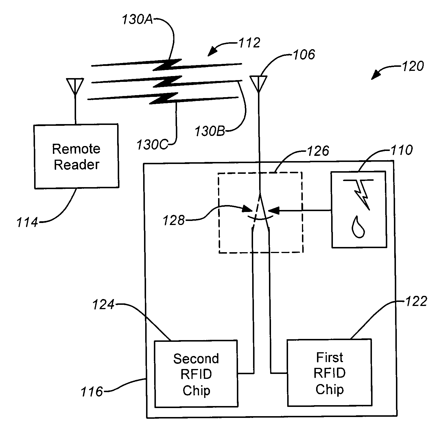
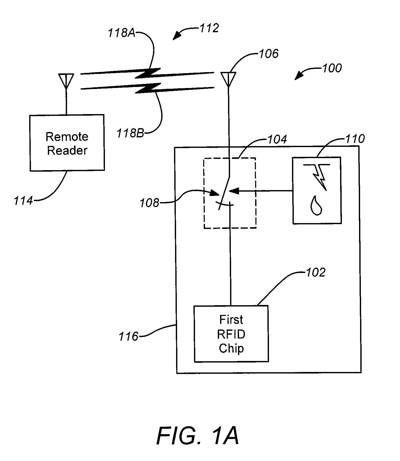
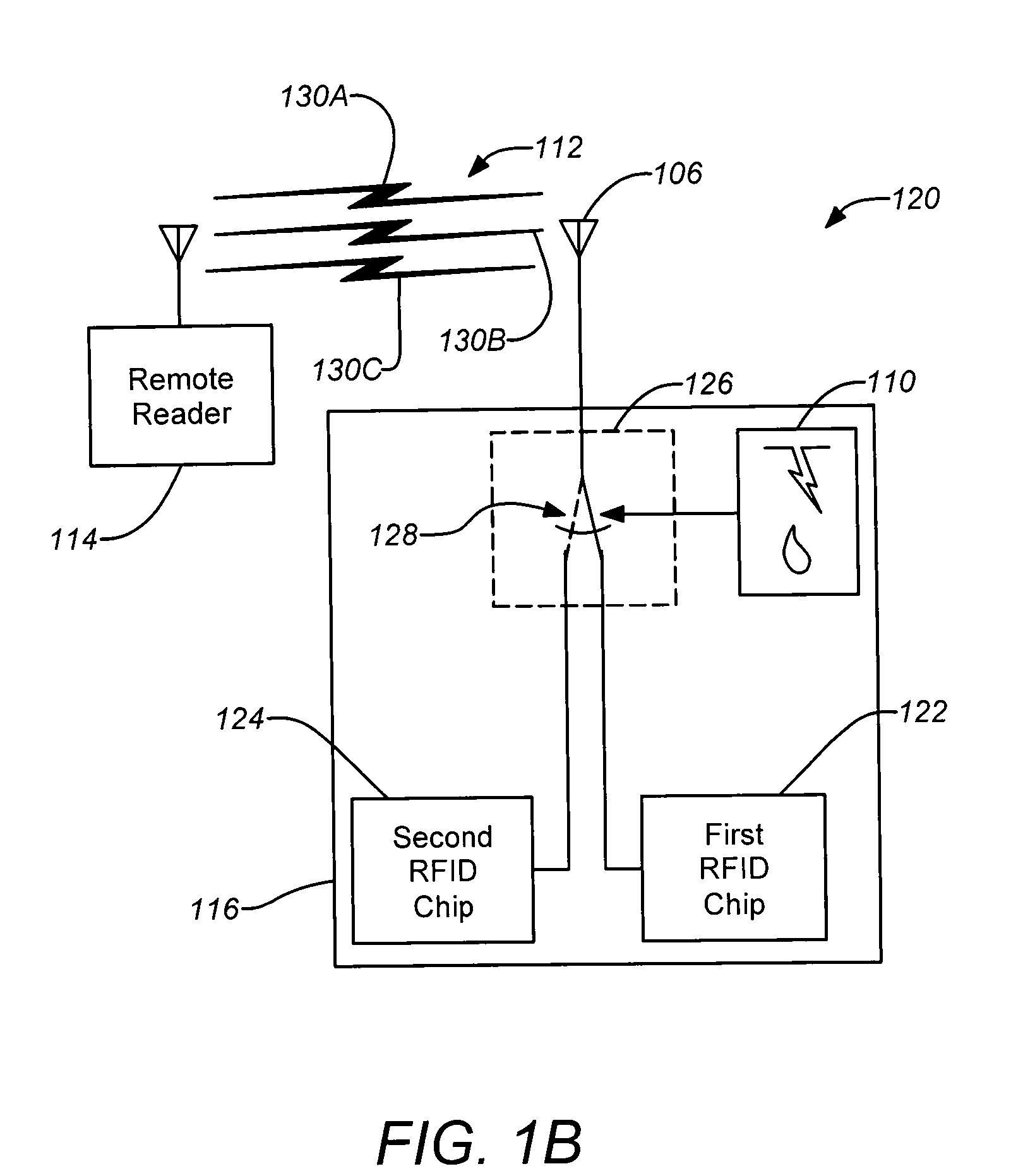
[0032]Embodiments of the disclosure can automatically detect the presence of an environment conducive to corrosion, which can enable the replacement of time-consuming visual inspection procedures with a much simpler and quicker nonintrusive inspection. Embodiments of the disclosure can take advantage of known radio frequency identification (RFID) technology to yield a passive and wireless interface for a sensor system. Such a system can be particularly useful in corrosion monitoring of aircraft, although embodiments of the disclosure are not limited to such applications. In some embodiments of the disclosure, conventional RFID technology can be applied to create a binary detector, capable of sensing moisture. The RFID-based corrosion and moisture detection techniques herein may be more generally described as RFID-based environmental structural sensing techniques.

[0033]Embodiments of the disclosure can enable inspections which do not require direct access to the stru...


PUM


Abstract

Structural health monitoring apparatuses and methods are disclosed. One or more structural health sensors may be used to disconnect and / or connect one or more RFID chips to an antenna such that wireless communication with the one or more RFID chips (or the absence of wireless communication) through the antenna indicates the structural health status. Example structural health sensors may be moisture detecting or fracture detecting. A remote reader may be used to establish the wireless communication with the one or more RFID chips to determine the structural health. The sensors and RFID chips may be passive and powered through the wireless communication from the remote reader. Such apparatuses and methods may be applied to any large structures requiring regular inspection, such as aircraft, ships, automobiles or buildings.

Description

CROSS-REFERENCE TO RELATED APPLICATIONS[0001]This application is related the following co-pending and commonly-assigned U.S. utility patent applications, which are all incorporated by reference herein:[0002]U.S. patent application Ser. No. 11 / 941,307, by Fay et al. filed Nov. 16, 2007, and entitled “FRACTURE DETECTING STRUCTURAL HEALTH SENSOR” (Attorney Docket No. 07-0716 / BOECP044);[0003]U.S. patent application Ser. No. 11 / 941,367, by Fay et al. filed Nov. 16, 2007, and entitled “CORROSION DETECTING STRUCTURAL HEALTH SENSOR” (Attorney Docket No. 07-0717 / BOECP045); and[0004]U.S. patent application Ser. No. 12 / 202,883, by Fay et al. filed Sep. 2, 2008, and entitled “HYBRID RESILIENT AND FRANGIBLE LAYERED STRUCTURAL HEALTH SENSOR” (Attorney Docket No. 08-0462 / BOECP052).BACKGROUND OF THE DISCLOSURE[0005]1. Field of the Disclosure[0006]This disclosure relates to structural testing. Particularly, this disclosure relates to techniques for monitoring the health of structural elements over t...

Claims


Application Information

Patent Timeline
Patent Type & Authority Applications(United States)
IPC IPC(8): G08B13/14
CPCG06K19/0717G08B21/20G06K2017/0077G06K19/0723
Inventor BOMMER, JASON P.PENA, GERARDOMALKIN, MATTHEW C.
Owner THE BOEING CO
Why Eureka
Try Eureka