Method and system for monopulse radar target angle determination

a monopulse radar and target angle technology, applied in the field of methods and systems for determining target angles, can solve the problems of reduced signal to noise ratio, and beam-shape loss of above approach

Inactive Publication Date: 2010-05-20
LOCKHEED MARTIN CORP
View PDF11 Cites 24 Cited by
  • Summary
  • Abstract
  • Description
  • Claims
  • Application Information

AI Technical Summary

Problems solved by technology

This approach suffers a beam-shape loss (i.e., a decreased signal to noise ratio due to decreased antenna gain), when the target is off the beam steering direction (i.e. off the center of the beam set).
As noted above, the above approach suffers from beam-shape loss.
The effects of beam-shape loss can be ameliorated by transmitting at higher power; however, the use of higher power transmi

Method used


Image

  • Method and system for monopulse radar target angle determination
  • Method and system for monopulse radar target angle determination
  • Method and system for monopulse radar target angle determination

Examples


Embodiment Construction

[0019]It is to be understood that the figures and descriptions of the present invention have been simplified to illustrate elements that are relevant for a clear understanding of the present invention, while eliminating, for the purpose of clarity, many other elements found in typical radar antenna arrays and signal processing systems. Those of ordinary skill in the art may recognize that other elements and / or steps are desirable and / or required in implementing the present invention. However, because such elements and steps are well known in the art, and because they do not facilitate a better understanding of the present invention, a discussion of such elements and steps is not provided herein.

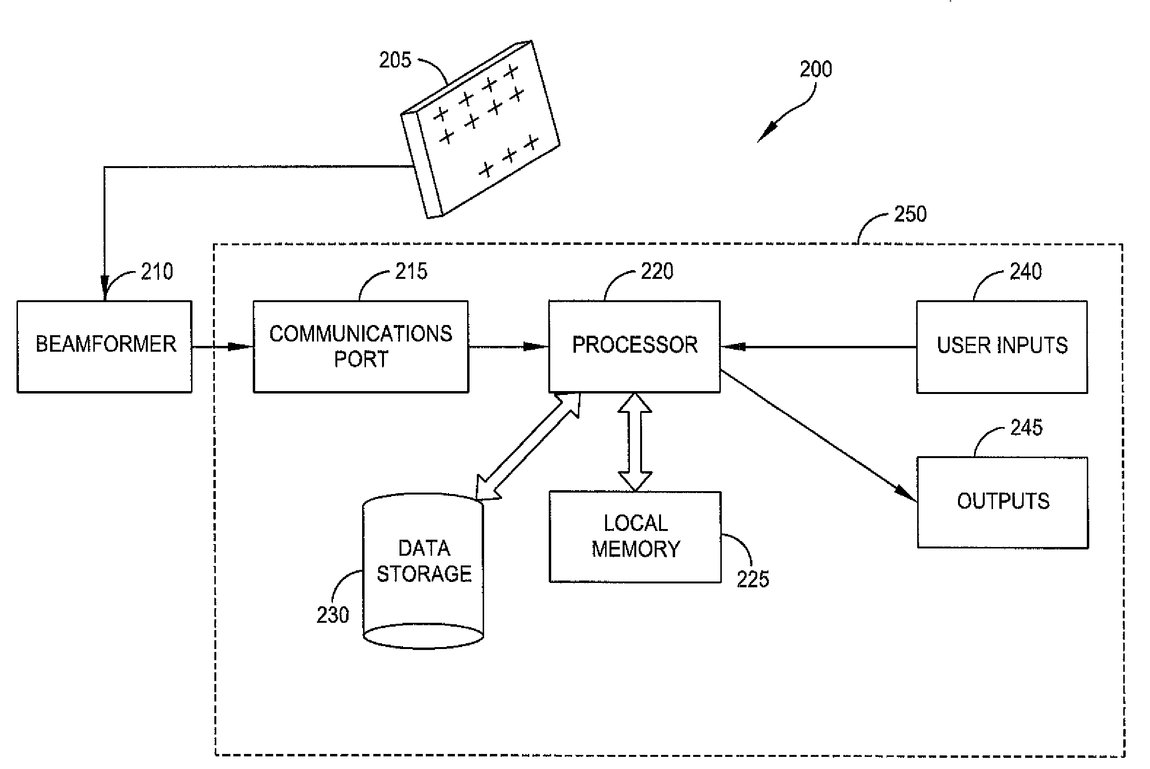
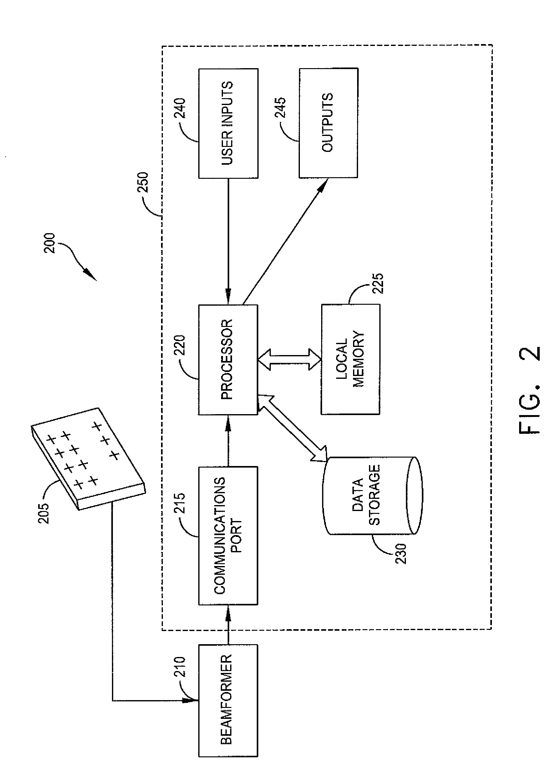
[0020]FIG. 2 is a schematic diagram of a system 200 for determining target angles based on data from a monopulse radar array 205. Radar array 205 may have any suitable shape, including rectangular. Element voltages are output by array 205 to beamformer 210. Beamformer 210 may be an analog bea...


PUM


Abstract

A method for determining target angles based on data received from a monopulse radar array antenna includes receiving from a beamformer that generates beams from signals generated by the monopulse radar antenna signals having data indicative of a sum beam, an azimuth difference beam, an elevation difference beam, and a delta-delta beam; based on the received signals, determining by the processor an azimuth monopulse ratio, an elevation monopulse ratio, a first complementary monopulse ratio based on the ratio of the delta-delta beam to the delta elevation beam, and a second complementary monopulse ratio based on the ratio of the delta-delta beam to the delta azimuth beam; determining an azimuth angle by the processor based on the azimuth monopulse ratio and the first complementary monopulse ratio; determining an elevation angle by the processor based on the elevation monopulse ratio and the second complementary monopulse ratio; providing an output signal indicative of the azimuth angle; and providing an output signal indicative of the elevation angle.

Description

FIELD OF INVENTION[0001]The present invention relates to methods and systems for determining target angles based on data from monopulse array-type radar systems.BACKGROUND[0002]Monopulse radar systems are used for searching for targets and for tracking targets. In monopulse radar systems, information concerning the angular location of a source or target is obtained by comparison of signals received in two or more simultaneous antenna beams. Referring to FIG. 1, monopulse radar systems have array radar antennas, such as antenna 12, that output antenna voltage data to beamformer 14. In searching for targets, such a system may interrogate a grid of angular positions using a single monopulse transmission beam set formed by beamformer 14. Beamformer 14 forms a detection sum beam, which is output to a processor, and processed using target detection logic 18 to determine whether a target is present. Beamformer 14 also forms orthogonal difference beams, i.e., azimuth difference beam and an ...

Claims


Application Information

Patent Timeline
IPC IPC(8): G01S13/44
CPCG01S13/4418
Inventor YU, KAI-BORKAUP, PETER G.
Owner LOCKHEED MARTIN CORP
Why Eureka
Try Eureka