

Tonescale compression for electroluminescent display
- Summary
- Abstract
- Description
- Claims
- Application Information
AI Technical Summary
Benefits of technology
Problems solved by technology
Method used
Image

Examples
Embodiment Construction
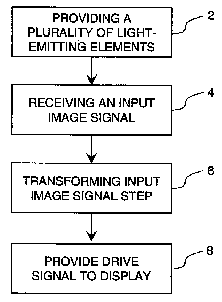
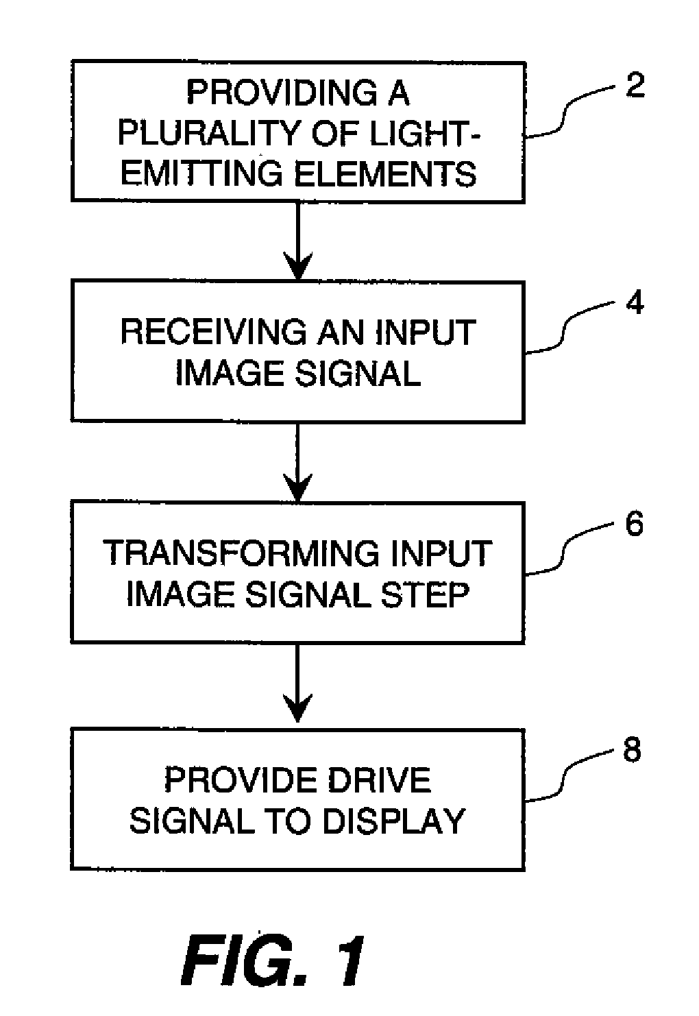
[0027]The need is met by providing a method for controlling an electroluminescent (EL) display system to produce an image for display that has reduced luminance to reduce burn-in on the display while maintaining visible contrast. This method includes the steps shown in FIG. 1. As shown in FIG. 1, an EL display including a plurality of EL emitters is provided 2 for emitting at least one color of light, the luminance of the light produced by each EL emitter being responsive to a respective drive signal. A respective input image signal is received 4 for each EL emitter. The input image signal is transformed 6 to a plurality of drive signals that that have a reduced peak frame luminance but maintain contrast in the displayed image to reduce burn-in by adjusting the drive signals to have reduced luminance provided by each pixel with the luminance decrease in a shadow range of the input image signals being less than the luminance decrease in a non-shadow range of the input image signals. ...
PUM
 Abstract
Description
Claims
Application Information