
Collimated visual display with elliptical front projection screen

a technology of front projection display and elliptical screen, which is applied in the field of display systems, can solve the problems of reducing image quality, particularly resolution and contrast ratio, and affecting the brightness and resolution of the top and bottom edges of the screen, and achieves the effect of improving luminance uniformity across the screen and high resolution imag

Inactive Publication Date: 2010-05-20
ESTERLINE BELGIUM BVBA
View PDF23 Cites 28 Cited by
  • Summary
  • Abstract
  • Description
  • Claims
  • Application Information

AI Technical Summary

Benefits of technology

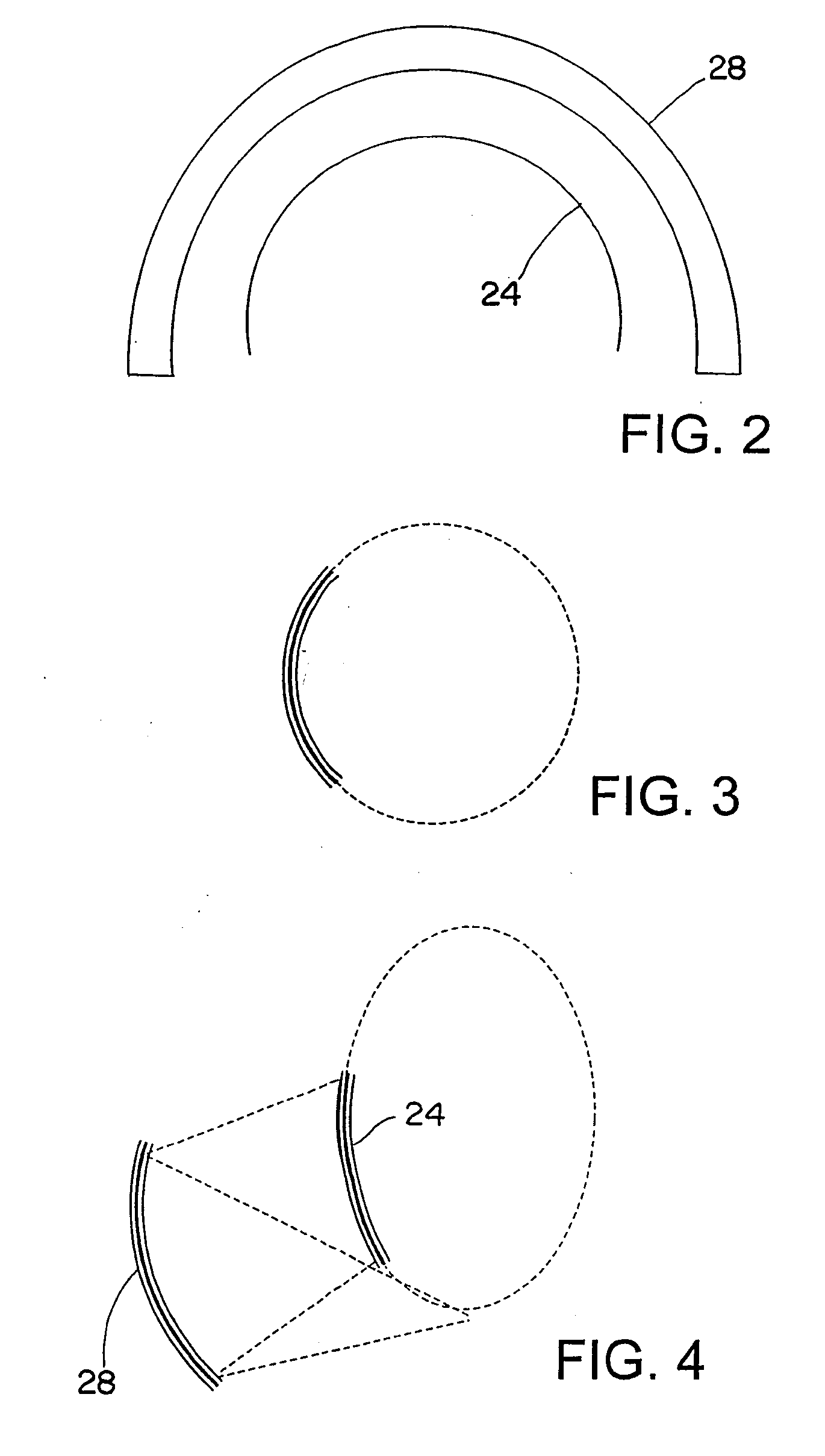
[0009]In an exemplary embodiment, the convex shape of the display surface corresponds to an ellipsoidal segment, which can be, for example, a segment corresponding to a portion of an ellipsoid between respective poles, or a portion of a prolate spheroid such that a horizontal extent of the screen is parallel to an equator of the spheroid. In the case of a prolate spheroid, the portion of the prolate spheroid can include a hemispherical portion whereby the screen is generally circular in cross-section about a first axis, and elliptical in cross-section about a second axis orthogonal to the first axis. The curvature of the display surface in the vertical direction of the image that is less than a curvature of the display surface in the horizontal direction of the image reduces the incident angle of light from the projector onto the screen, as compared to a spherical screen thereby resulting in a higher resolution image and improved luminance uniformity across the screen. The reflector can be a spherical collimating mirror. The system can further include at least one projector for projecting the image onto the screen.

Problems solved by technology

Such a cross reflection can degrade image quality, particularly resolution and contrast ratio.
This presents some difficulty in placing a large cockpit, or cab, in a multi-projector system.
Front projection display systems employing spherical screens, however, suffer from diminished brightness and resolution at the top and bottom edges of the screen.

Method used


Image

  • Collimated visual display with elliptical front projection screen
  • Collimated visual display with elliptical front projection screen
  • Collimated visual display with elliptical front projection screen

Examples


Embodiment Construction

[0020]Because the various aspects of the invention were conceived and developed for use in front projection collimated display systems, such as used in flight simulators and the like, it will be herein described chiefly in this context. However, the principles of the invention in their broader aspects can be adapted to other types of projection systems.

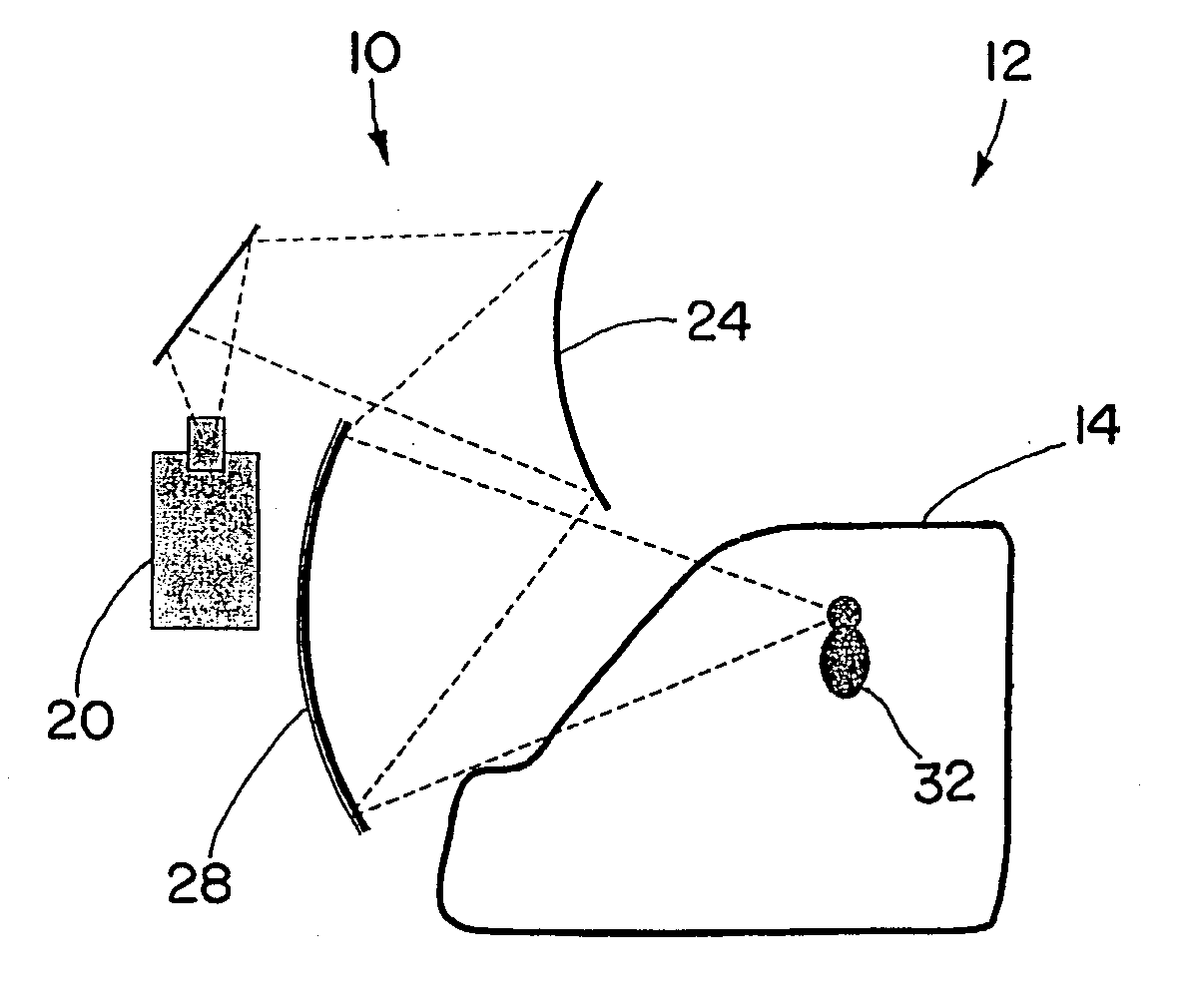
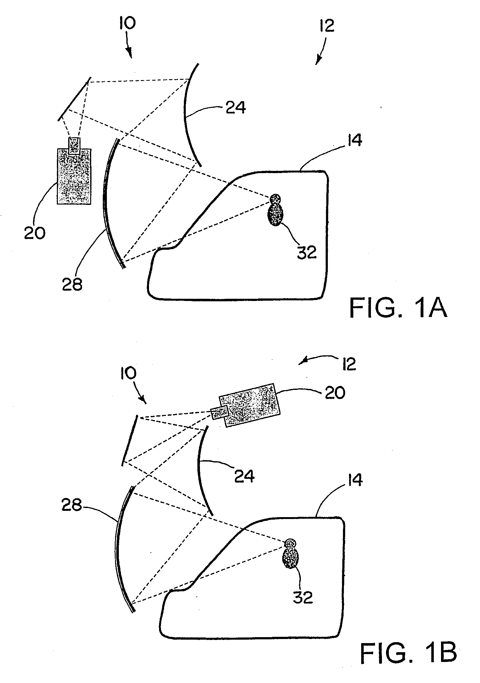
[0021]Referring now in detail to the drawings and initially to FIGS. 1A and 1B, two exemplary front-projection collimating display systems according to the invention are designated generally by reference numeral 10. The display system 10, which in the illustrated embodiment is part of a flight simulator 12 including the nose of an aircraft fuselage, or cockpit, 14, includes at least one projector 20, a curved front projection screen 24, and a reflector 28, which in the illustrated embodiment is a spherical collimating mirror. The screen 24 and mirror 28 each have a vertical and horizontal axis, and the screen 24 is vertically offset f...


PUM


Abstract

A front-projection display system having a screen with improved brightness and / or resolution of an image displayed on outer portions thereof. The screen has a display surface that is generally a convex shape having a curvature of the display surface in the vertical direction of an image projected thereon that is less than a curvature of the display surface in the horizontal direction.

Description

FIELD OF THE INVENTION[0001]The invention herein described relates generally to display systems, and more particularly to display systems using projectors.BACKGROUND[0002]Collimated displays systems have long been used in wide-bodied aircraft simulators. The primary components of collimated displays are at least one projector, a projection screen, typically spherical, placed above and in front of the cockpit or cab of the simulator on which the projector projects an image, and a collimating mirror in front of and wrapping around the cockpit or cab for providing a large horizontal field-of-view. The projection screen can be either front or rear projected, and the projected image is viewed via the collimating mirror.[0003]A front projection system has a number of advantages, as compared to a back projection system. Front projection screens are generally more economical to produce, and eliminate the problem of specular cross reflection prevalent in back projection curved screens with a...

Claims


Application Information

Patent Timeline
Patent Type & Authority Applications(United States)
IPC IPC(8): G03B21/28G03B21/60
CPCG09B9/32G03B21/28
Inventor OREN, MOSHE
Owner ESTERLINE BELGIUM BVBA
Learn More