Ceramic capacitor and electronic component including the same

a ceramic capacitor and electronic component technology, applied in the field of ceramic capacitors, can solve the problems of mounting substrate vibration, dc-dc converter unavoidably producing ripple voltage on the operating principle, and difficulty in reducing power consumption, so as to achieve the effect of preventing substrate noise much more effectively and satisfactorily

Active Publication Date: 2010-05-20
MURATA MFG CO LTD
View PDF4 Cites 100 Cited by
  • Summary
  • Abstract
  • Description
  • Claims
  • Application Information

AI Technical Summary

Benefits of technology

[0010]In view of the above, preferred embodiment of the present invention provide a capacitor that is mounted on a substrate and is arranged to prevent substrate noise much more effectively and satisfactorily.

Problems solved by technology

This has made it difficult to reduce power consumption.
Also, the DC-DC converter unavoidably produces a ripple voltage on the operating principles thereof.
As a result, the mount substrate produces vibration.
However, when the inventors of the present application conducted specific research on this device, it turned out that the capacitor 100 could not sufficiently restrain propagation of vibration thereof to the substrate and therefore could not sufficiently restrain substrate noise.

Method used


Image

  • Ceramic capacitor and electronic component including the same
  • Ceramic capacitor and electronic component including the same
  • Ceramic capacitor and electronic component including the same

Examples


first preferred embodiment

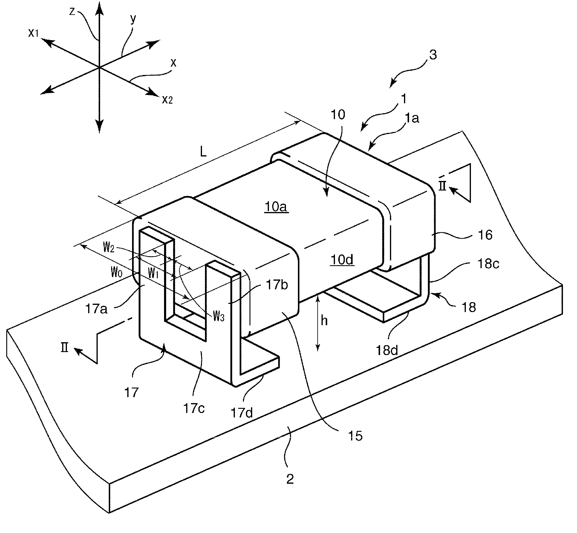
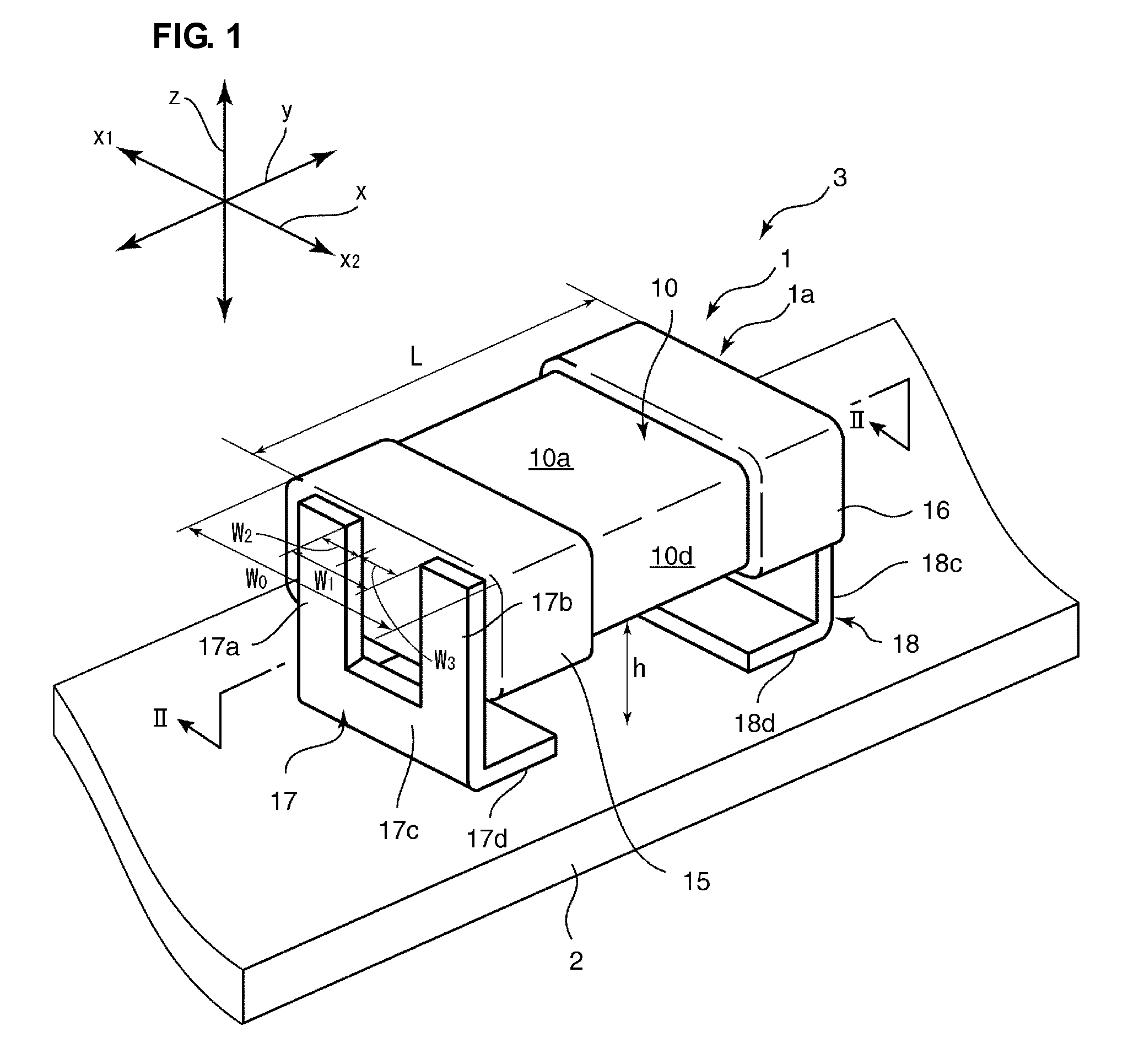
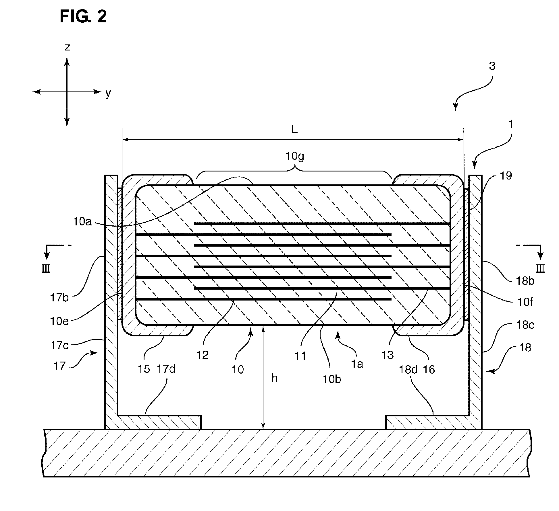
[0041]FIG. 1 is a perspective view of an electronic component 3 according to a first preferred embodiment of the present invention. FIG. 2 is a schematic sectional view cut along line II-II of FIG. 1. FIG. 3 is a schematic sectional view cut along line III-III of FIG. 2.

[0042]As shown in FIG. 1, the electronic component 3 includes a substrate 2 and a ceramic capacitor 1 mounted on the substrate 2. The substrate 2 is a substrate having an electronic circuit, to which the ceramic capacitor 1 is electrically connected, disposed on a surface thereof or therein. The substrate 2 is not limited to a particular type of substrate. For example, the substrate 2 does not necessarily need to be flexible or may be a flexible sheet. For example, the substrate 2 may be a flexible printed circuit (FPC) having an electronic circuit printed thereon.

[0043]As shown in FIGS. 1 to 3, the electronic component 1 includes a capacitor body 10 that is substantially made of a dielectric material. As shown in FI...

first experimental example

[0083]The ceramic capacitor described in the above-mentioned first preferred embodiment was manufactured in a multiple number at various W1 / W0 ratios. Subsequently, each of the manufactured ceramic capacitors was bonded to a substrate that has a thickness of about 1.6 mm, a length of about 40 mm, and a width of about 100 mm and is made of glass epoxy (FR-4), and the sound pressure level of substrate noise made at that time was measured. As for the design parameters other than W1 / W0, same values were set for each ceramic capacitor. For each ceramic capacitor, the width dimension along the first directions x, of the capacitor body was set to about 3.2 mm, the length dimension thereof along the second directions y was set to about 2.5 mm, and the height dimension thereof was set to about 2.0 mm. The first and second external electrodes were formed of Cu, and a Ni-plated layer and a Sn-plated layer were formed on a surface of each external electrode. The first and second electrode termi...

second experimental example

[0086]Various ceramic capacitors having a configuration similar to that of the first experimental example were manufactured while changing only h / L. Subsequently, as in the above-mentioned first experimental example, the sound level of substrate noise was measured for each ceramic capacitor. In this experimental example, W1 / W0 was fixed to about 0.3.

[0087]FIG. 11 shows the measurement results. Note that the values of h / L at points A to D in FIG. 11 were about 0.10, about 0.175, about 0.263, and about 0.35, respectively.

[0088]From the results shown in FIG. 11, it is understood that by setting h / L to about 0.1 or more, the sound level of substrate noise can be prevented much more effectively and satisfactorily. Specifically, it is understood that by setting h / L to about 0.1 or more, the sound level of substrate noise can be reduced by about 40% or more compared with that in a case where h / L is about 0.

[0089]In the range where h / L exceeds about 0.35, the sound level of substrate noise ...


PUM

PropertyMeasurementUnit
thicknessesaaaaaaaaaa
widthaaaaaaaaaa
lengthaaaaaaaaaa

Abstract

In a ceramic capacitor, first and second electrode terminals each include a bonded-to-substrate portion, a first bonded-to-electrode portion bonded to a first edge of one of first and second external electrodes, a second bonded-to-electrode portion bonded to a second edge of the one of first and second external electrodes and disposed at a distance from the first bonded-to-electrode portion in the first directions, and a connecting portion connecting the first and second bonded-to-electrode portions and the bonded-to-substrate portion. W1 / W0 is about 0.3 or more, and h / L is about 0.1 or more.

Description

BACKGROUND OF THE INVENTION[0001]1. Field of the Invention[0002]The present invention relates to a ceramic capacitor and, in particular, to a ceramic capacitor mounted on a substrate with a pair of external electrodes therebetween, and an electronic component including the ceramic capacitor.[0003]2. Description of the Related Art[0004]In recent years, with increases in performance of mobile electronic apparatuses, such as cell phones and notebook personal computers, the performance of a CPU or the like mounted on such a mobile electronic apparatus has been increased. This has made it difficult to reduce power consumption. On the other hand, mobile electronic apparatuses have been strongly required to be driven by a battery for a longer time.[0005]Accordingly, mobile electronic apparatuses have been strongly required to increase the conversion efficiency of the power supply unit thereof. As the power supply units of mobile electronic apparatuses, DC-DC converters having good conversi...

Claims


Application Information

Patent Timeline
Patent Type & Authority Applications(United States)
IPC IPC(8): H01G4/228
CPCH01G2/06H01G4/228H01G4/232H05K2201/10946H05K3/3426H05K2201/10636H01G4/30Y02P70/50
Inventor OTSUKA, HIDEKIYOSHIDA, KAZUHIRO
Owner MURATA MFG CO LTD
Why Eureka
Try Eureka