Power output apparatus

a technology of power output and power supply, which is applied in the direction of electric propulsion mounting, battery/fuel cell control arrangement, gearing, etc., can solve the problems of complex structure, difficult loading to a vehicle, and high cost, and achieve the effect of short tim

Inactive Publication Date: 2010-05-20
HONDA MOTOR CO LTD
View PDF7 Cites 70 Cited by
  • Summary
  • Abstract
  • Description
  • Claims
  • Application Information

AI Technical Summary

Benefits of technology

[0216]According to the power output apparatus of the fifty-third aspect, if there is a defect in at least one of the electric motor, the electric storage device, the con

Problems solved by technology

Therefore, when the engine torque is necessarily divided and the same torque as the engine torque is transmitted to the driving shaft 108, there is a problem in that it i

Method used


Image

  • Power output apparatus
  • Power output apparatus
  • Power output apparatus

Examples


first embodiment

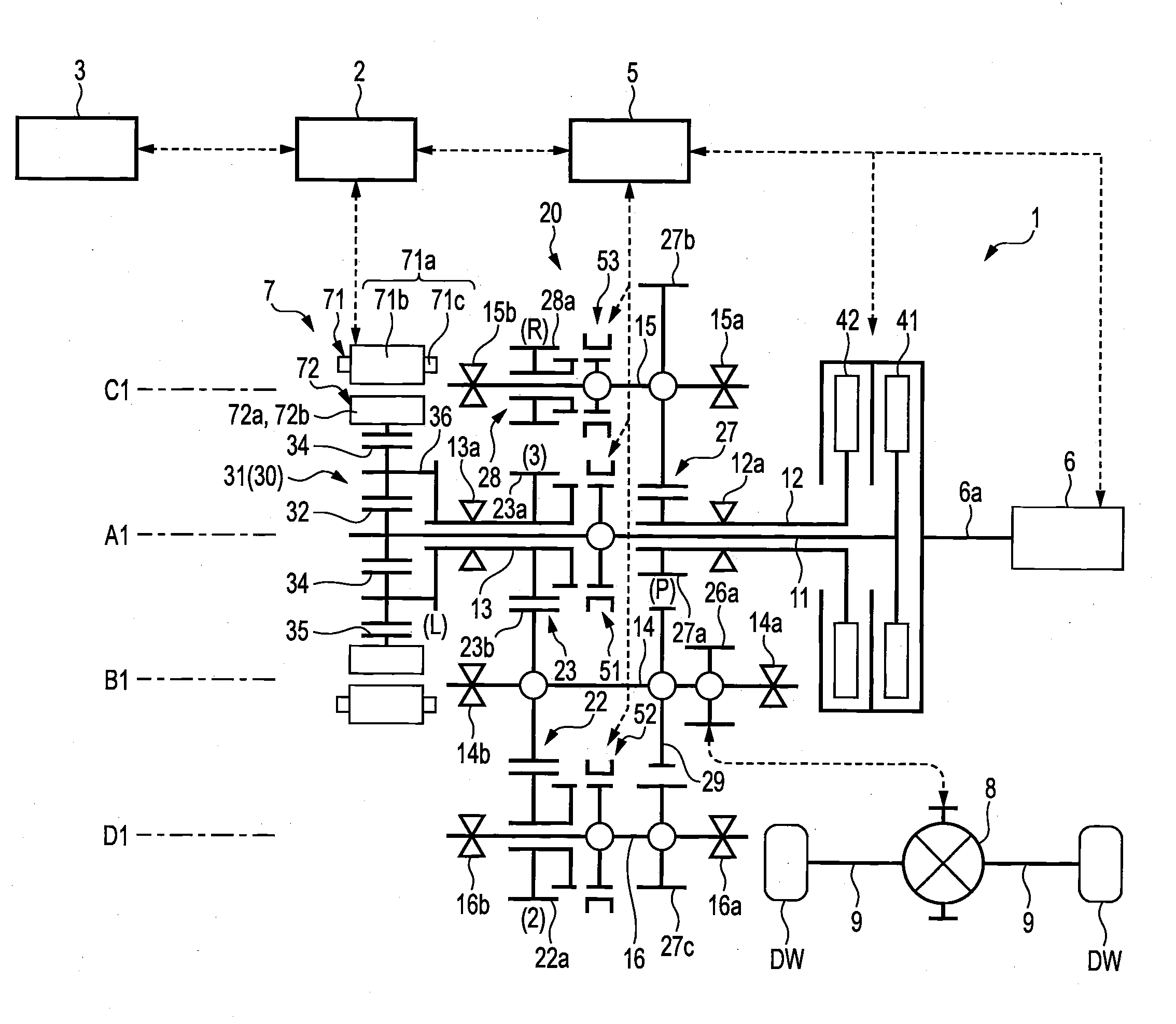
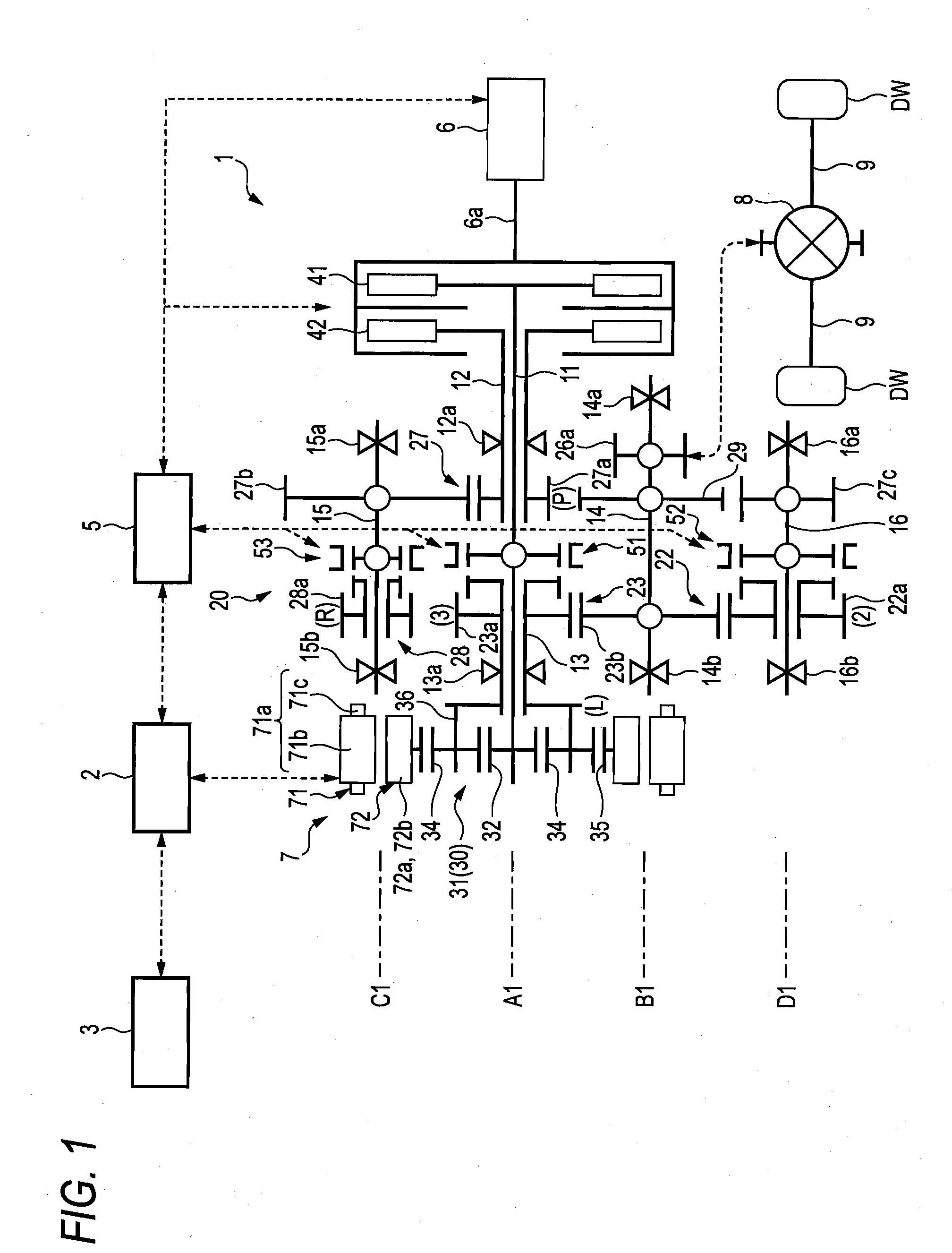
[0263]FIG. 1 schematically shows a power output apparatus 1 according to a first embodiment of the invention. The power output apparatus 1 drives driving wheels DW and DW via driving shafts 9 and 9 of a vehicle (not shown), and includes an internal combustion engine (hereinafter referred to as an “engine”) 6 that is a driving source, an electric motor (hereinafter referred to as a “motor”) 7, a transmission 20 for transmitting power to the driving wheels DW and DW attached to the driving shafts 9 and 9, a power combination mechanism 30, and a differential gear mechanism 8. In addition, in the following description, power is obtained by multiplying torque by number of revolutions, i.e., “power (output)=torque×number of revolutions.”

[0264]The engine 6 is, for example, a gasoline engine, and a crankshaft 6a of the engine 6 is provided with a first clutch (a first connecting / disconnecting section) and a second clutch 42 (a second connecting / disconnecting section).

[0265]The motor 7 has a...

second embodiment

[0332]Next, a power output apparatus 1A according to a second embodiment of the invention will be described with reference to FIGS. 21 to 37. In addition, the power output apparatus 1A of the second embodiment has the same construction as the power output apparatus 1 of the first embodiment except that the transmission 20A includes a gear pair 24 for fourth speed whose speed reduction ratio is smaller than that of the speed change gear pair 23 for a third speed, and a gear pair 25 for fifth speed whose speed reduction ratio is smaller than that of the gear pair 24 for fourth speed. For this reason, the same portions as or portions equivalent to those of the power output apparatus 1 of the first embodiment are denoted by the same or equivalent reference numerals, and the description thereof is simplified or omitted.

[0333]FIG. 21 schematically shows the power output apparatus 1A according to the second embodiment of the invention.

[0334]In a transmission 20A in the power output apparat...

third embodiment

[0386]Next, a power output apparatus according to a third embodiment of the invention will be described with reference to FIG. 38. In addition, the power output apparatus 1B of the third embodiment has the same construction as the power output apparatus 1A of the second embodiment except that the constructions of the transmissions are different from each other. For this reason, the same portions as or portions equivalent to those of the power output apparatus 1A of the second embodiment are denoted by the same or equivalent reference numerals, and the description thereof is simplified or omitted.

[0387]Accordingly, the transmission 20B of this embodiment is adapted such that the driving gear 22a for second speed and the driving gear 24a for fourth speed that are even-numbered speed change stages are provided around the first main shaft 11 (first transmission shaft) that is one transmission shaft of the two transmission shafts, the driving gear 21a for first speed and, driving gear 23...


PUM


Abstract

A power output apparatus 1 to 1D including an engine 6, a motor 7, and a transmission 20 to 20D having two transmission shafts connected to the engine 6 is provided. The transmission includes a power combination mechanism 30 adapted so as to be able to rotate first to third elements differentially from each other. The first element is connected to any one of the two transmission shafts, the second element is connected to a driving shaft 9 or 9, and the third element is connected to the motor 7. The second element combines the power transmitted from the first element and the power transmitted from the third element, and transmits the combined power to the driving shaft 9 and 9. The other transmission shaft of the two transmission shafts transmits power to the driving shaft 9 or 9 without going via the power combination mechanism 30.

Description

CROSS-REFERENCE TO RELATED APPLICATIONS[0001]This application is based on and claims priority under 35 U.S.C. §119 from Japanese Patent Application Nos. 2008-296011 filed on Nov. 19, 2008, 2009-048074 filed on Mar. 2, 2009 and 2009-245770 filed on Oct. 26, 2009.BACKGROUND OF THE INVENTION[0002]1. Technical Field[0003]The present invention relates to a power output apparatus, and particularly, to a power output apparatus of a hybrid vehicle.[0004]2. Related Art[0005]Conventionally, for example, a power output apparatus of a hybrid vehicle including an engine, a motor, and a planetary gear mechanism composed of a sun gear, a ring gear, a plurality of planetary gears which engages with these sun gear and ring gear, and a carrier which supports the plurality of planetary gears is known (for example, refer to Patent Document 1).[0006]As shown in FIG. 44, a power output apparatus 100 described in the above Patent Document 1 connects a first motor 104 serving as a generator to a sun gear 1...

Claims


Application Information

Patent Timeline
IPC IPC(8): B60W20/00F16H48/06F16H37/06
CPCB60K6/365B60K6/48B60K6/547F16H3/006F16H3/725Y10T74/19051Y10T74/19288Y10T477/23Y10T74/19223Y10T74/19228Y02T10/6221B60L15/20B60L15/2054B60L15/2072B60L2240/421B60L2240/423B60L2240/441B60L2240/443B60L2240/486B60L2240/507B60L2240/545B60L2260/26B60L2270/145Y02T10/70Y02T10/72B60L50/16B60L58/12Y02T10/62Y02T10/64Y02T10/7072
Inventor IKEGAMI, TAKEFUMIABE, NORIYUKIKOYAMA, SHIGERUSAKAI, ATSUHIROFUJIMOTO, SHINJI
Owner HONDA MOTOR CO LTD
Why Eureka
Try Eureka