Balloon catheter for crossing a chronic total occlusion

a total occlusion, balloon catheter technology, applied in balloon catheters, other medical devices, surgery, etc., can solve the problems of affecting the treatment of patients, and affecting the treatment effect of patients,

Inactive Publication Date: 2010-05-20
MEDTRONIC VASCULAR INC
View PDF16 Cites 66 Cited by
  • Summary
  • Abstract
  • Description
  • Claims
  • Application Information

AI Technical Summary

Problems solved by technology

The tortuous configuration of the arteries may present difficulties to a clinician in advancement of the balloon catheter to a treatment site.
In addition, in some instances, the extent to which the lumen is narrowed at the treatment site is so severe that the lumen is completely or nearly completely obstructed, which may be described as a total occlusion.
This fibrous cap may present a surface that is difficult to penetrate with a conventional medical guidewire such that one method of crossing a chronic total occlusion includes utilizing a stiffer guidewire to create a new channel through the occlusion.
Due to the fibrous cap of the total occlusion, a stiffer guidewire still may not be able to cross the occlusion and the distal end of the guidewire may buckle or prolapse within the vessel when force is applied.
Further, even if a stiffer guidewire can penetrate the proximal fibrous cap of the total occlusion, it may not be able to completely cross the occlusion due to multiple non-functional channels that often occur throughout the occlusion, which if entered by the guidewire lead to dead-end pathways and / or to the creation of false tracts within the occlusion and the problems attendant thereto.
Another challenge with the treatment of chronic total occlusions is that even after a guidewire successfully crosses the occlusion, the clinician may not be able to advance a dilatation balloon over the guidewire due to the fibrocalcific composition of the chronic total occlusion.

Method used


Image

  • Balloon catheter for crossing a chronic total occlusion
  • Balloon catheter for crossing a chronic total occlusion
  • Balloon catheter for crossing a chronic total occlusion

Examples


Embodiment Construction

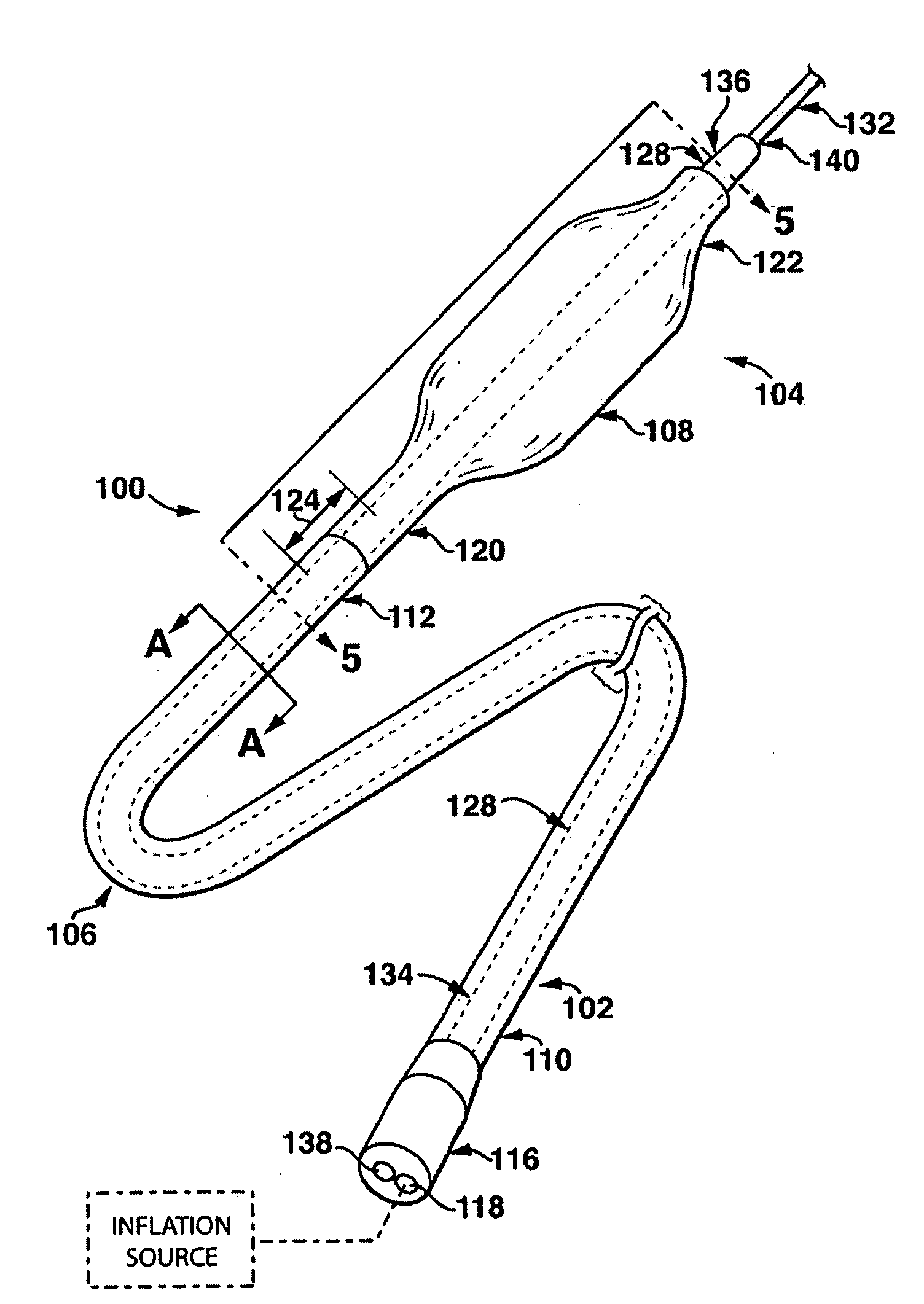
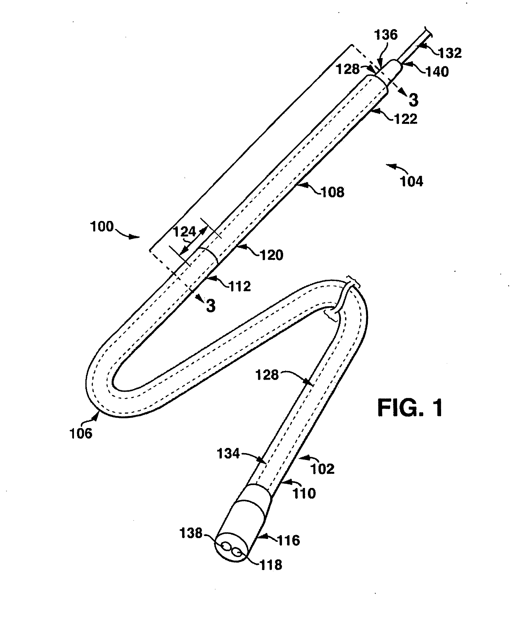
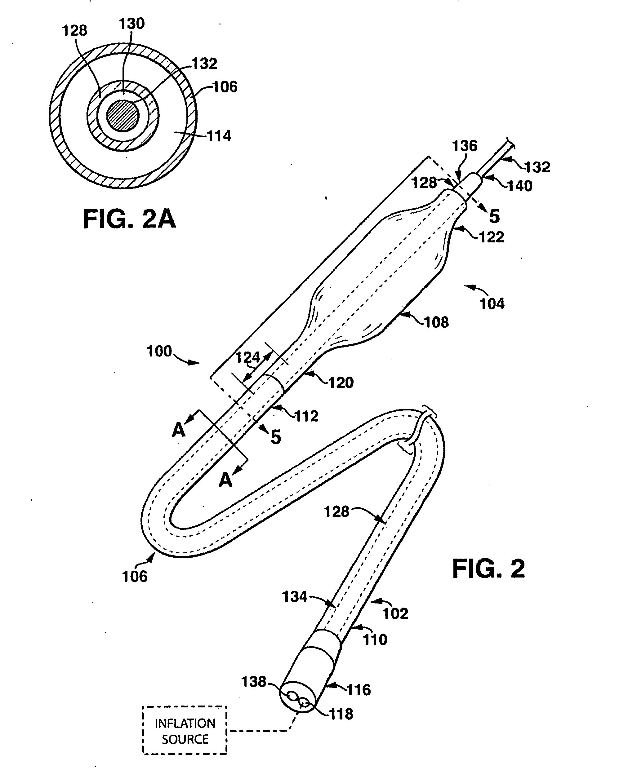
[0016]Specific embodiments of the present invention are now described with reference to the figures, wherein like reference numbers indicate identical or functionally similar elements. The terms “distal” and “proximal” are used in the following description with respect to a position or direction relative to the treating clinician. “Distal” or “distally” are a position distant from or in a direction away from the clinician. “Proximal” and “proximally” are a position near or in a direction toward the clinician.

[0017]The following detailed description is merely exemplary in nature and is not intended to limit the invention or the application and uses of the invention. Although the description of the invention is in the context of treatment of blood vessels such as the coronary, carotid and renal arteries, the invention may also be used in any other body passageways where it is deemed useful. Furthermore, there is no intention to be bound by any expressed or implied theory presented in ...


PUM


Abstract

A balloon catheter is disclosed including a “no-fold” balloon at a distal end thereof that surrounds a distal portion of a guidewire shaft having a compliant shaft or tubular section for selectively gripping a guidewire there within. Upon introduction of inflation fluid at low pressure values, the compliant shaft section of the guidewire shaft is radially compressed to “lock” onto the guidewire while an outer diameter of the no-fold balloon remains unchanged. The simultaneous compression of the compliant shaft section against a guidewire located within the guidewire lumen and the filling of the balloon with inflation fluid without expanding the balloon provides a clinician with a conjoined balloon catheter and guidewire ensemble that together may be pushed through a tight stenosis such as a chronic total occlusion (CTO).

Description

FIELD OF THE INVENTION[0001]The invention relates generally to a balloon catheter having improved pushability for crossing tight cardiovascular stenoses such as a chronic total occlusion.BACKGROUND OF THE INVENTION[0002]Cardiovascular disease, including atherosclerosis, is the leading cause of death in the United States. One method for treating atherosclerosis and other forms of arterial lumen narrowing is percutaneous transluminal angioplasty, commonly referred to as “angioplasty” or “PTA,” or “PTCA” when performed in the coronary arteries. The objective in angioplasty is to restore adequate blood flow through the affected artery, which may be accomplished by inflating a balloon of a balloon catheter within the narrowed lumen of the artery to dilate the vessel.[0003]The anatomy of arteries varies widely from patient to patient. Often a patient's arteries are irregularly shaped, highly tortuous and very narrow. The tortuous configuration of the arteries may present difficulties to a...

Claims


Application Information

Patent Timeline
Patent Type & Authority Applications(United States)
IPC IPC(8): A61M25/10A61F2/958
CPCA61M25/0075A61M2025/09125A61M25/10
Inventor MCANDREW, EAMONN JOSEPH
Owner MEDTRONIC VASCULAR INC
Why Eureka
Try Eureka