Hard and Soft Tip Intraocular Lens Injector System and Method

a technology of injector system and intraocular lens, which is applied in the field of intraocular lens injector system, can solve the problems of not providing as secure and controlled engagement profile with the iol as does the rigid plunger tip lens engagement surface, and the plunger tip may damage the iol

Inactive Publication Date: 2010-05-20
BAUSCH & LOMB INC
View PDF72 Cites 36 Cited by
  • Summary
  • Abstract
  • Description
  • Claims
  • Application Information

AI Technical Summary

Benefits of technology

[0006]The present invention addresses, in one or more embodiments thereof, the above-described need by providing an IOL injector system including a plunger assembly slidably disposed within the lumen of an injector body extending to an injector tip having an opening. The plunger assembly includes a first component comprising a rigid body having a lens engagement surface at its distal end and an interference feature. A compressible sleeve is slidably positioned on the first component. The plunger assembly further includes a second component having proximal and distal ends and a central opening extending longitudinally therebetween. The first component is slidably disposed within the central opening of the second component. The first component, the second component, and the sleeve are configured to slide within the lumen in a first state in which the engagement surface is disposed distally of the compressible sleeve and the IOL is carried in the lumen by the rigid lens engagement surface, thus having the benefit of a secure and controlled lens engagement profile as described above.

Problems solved by technology

Since IOLs are very delicate, there is the chance the plunger tip may damage the IOL as it is pushed, compressed and ultimately ejected from the injector tip by the plunger.
However, a rigid lens engagement surface also has the disadvantage of possibly damaging the IOL due to the unyielding characteristic of the rigid material, particularly at the point of peak delivery force at the tip opening as described above.
On the other hand, a plunger tip having a lens engagement surface made of a soft material has the benefit of yielding to the lens during the period of peak delivery force which reduces the risk of damaging the lens, but has the disadvantage of not providing as secure and controlled engagement profile with the IOL as does a rigid plunger tip lens engagement surface.

Method used


Image

  • Hard and Soft Tip Intraocular Lens Injector System and Method
  • Hard and Soft Tip Intraocular Lens Injector System and Method
  • Hard and Soft Tip Intraocular Lens Injector System and Method

Examples


Embodiment Construction

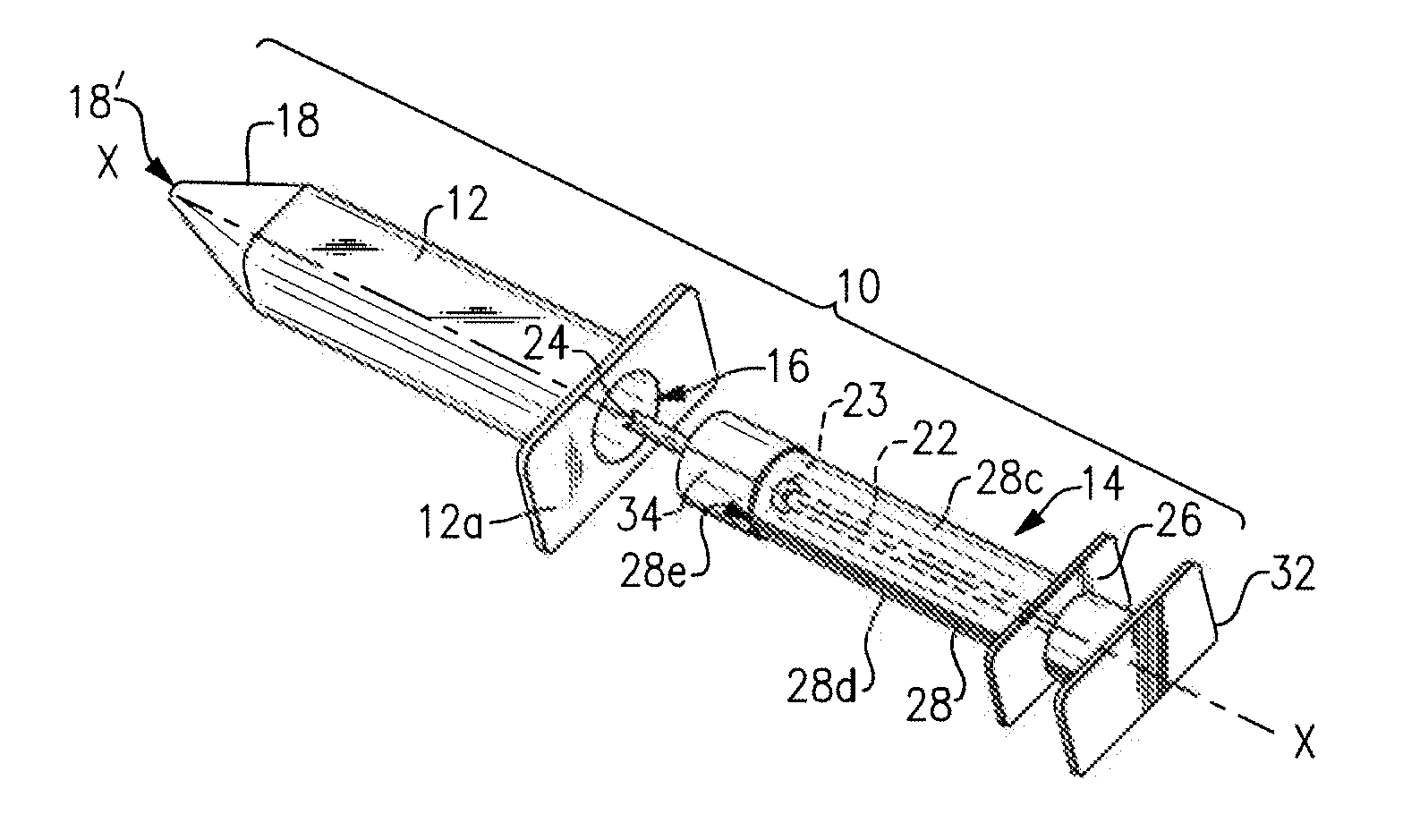
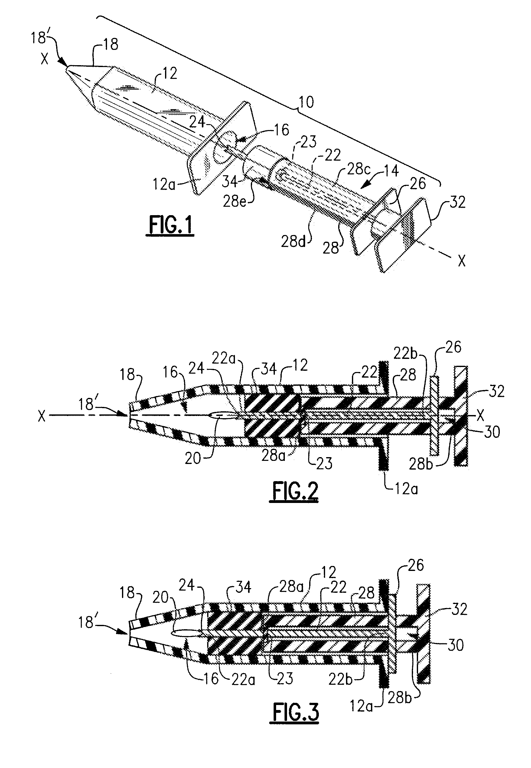
[0017]An IOL is implanted in an eye by a surgeon with the aid of an injector tool such as IOL injector system 10. Injector system 10 includes an injector body 12 and a plunger assembly 14 which is slidably disposed within a lumen 16 of injector body 12. Lumen 16 of injector body 12 extends to an injector tip 18 terminating in an opening 18′ wherethrough an IOL 20 may pass and thereby expressed from injector system 10 and into an eye (not shown).

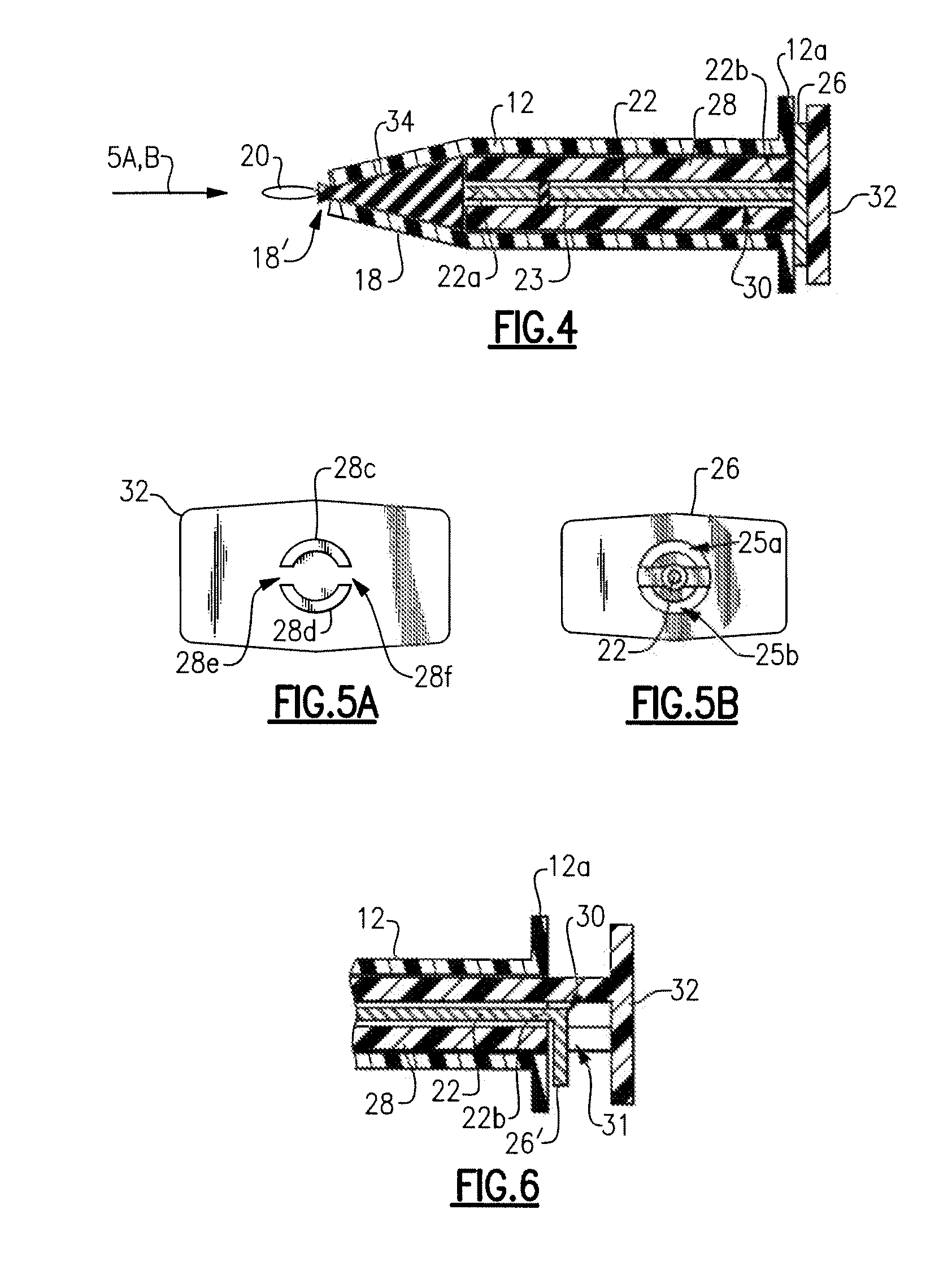
[0018]Plunger assembly 14 includes a first component 22 comprising a shaft having a lens engagement surface 24 at distal end 22a thereof. First component 22 including lens engagement surface 24 is made from any suitable rigid material such as a metal or plastic, for example. An interference feature 26 is provided at proximal end 22b thereof for the purpose to be explained below.

[0019]Plunger assembly 14 further includes a second component 28 having a central opening 30 extending longitudinally between distal and proximal ends 28a, 28b, respec...


PUM


Abstract

IOL injector system and method for injecting an IOL into an eye which incorporates the benefits of both a rigid and soft plunger tip lens engagement surface while at the same time reduces or eliminates the disadvantages associated therewith.

Description

BACKGROUND OF THE INVENTION[0001]The present invention relates to intraocular lens injector systems, and more particularly relates to an intraocular lens (“IOL”) injector system having a rigid lens engagement surface for advancing the IOL within the injector body during a first stage of plunger advancement, and a soft lens engagement surface for advancing the IOL during a second stage of plunger advancement which concludes by expressing the IOL from the injector and into an eye.[0002]IOLs are well known and are used for implanting into an eye to replace the eye's extracted natural lens in a common surgical procedure known as cataract surgery. There are many different types of IOLs available and the surgeon chooses the IOL according to one or more factors including, for example, the physiology and refractive needs of the patient's eye. IOLs are configured with an optic and one or more haptics extending from the optic which act as anchoring elements to properly position the IOL within...

Claims


Application Information

Patent Timeline
Patent Type & Authority Applications(United States)
IPC IPC(8): A61F9/007
CPCA61F2/167A61F2/1662A61F9/007A61F2/14A61M5/14A61M31/00
Inventor WAGNER, CHRISTOPHER E.
Owner BAUSCH & LOMB INC
Why Eureka
Try Eureka