Repair method for tbc coated turbine components

a technology of turbine components and coatings, applied in the direction of machines/engines, mechanical equipment, superimposed coating processes, etc., can solve the problems of limiting the effective service life of components, cracks, damage, or material loss, and components that are commonly developed defects

Inactive Publication Date: 2010-05-27
GENERAL ELECTRIC CO
View PDF8 Cites 29 Cited by
  • Summary
  • Abstract
  • Description
  • Claims
  • Application Information

AI Technical Summary

Problems solved by technology

Components in the hot section are exposed during operation to a high temperature, corrosive gas stream that limits their effective service life.
Despite the use of protective coatings, such components commonly develop defects such as cracks, damage, or material loss during service.
These two processes have a number of negative aspects, including low labor cost productivity, process variance and rework because of the manual nature of the processes, and component wall loss during chemical stripping which results in a high scrap rate.

Method used


Image

  • Repair method for tbc coated turbine components
  • Repair method for tbc coated turbine components
  • Repair method for tbc coated turbine components

Examples


Embodiment Construction

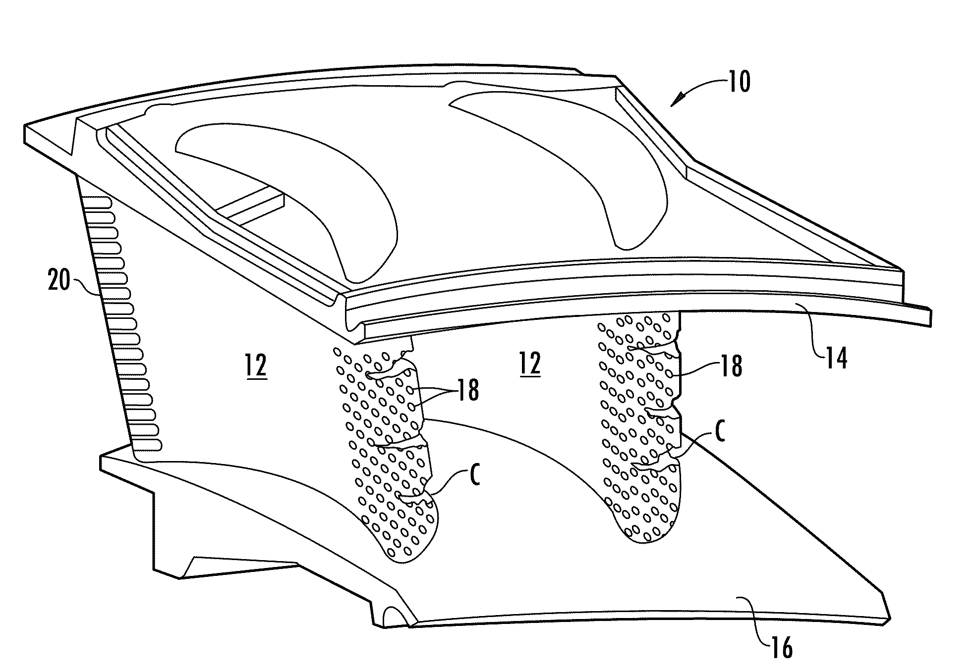
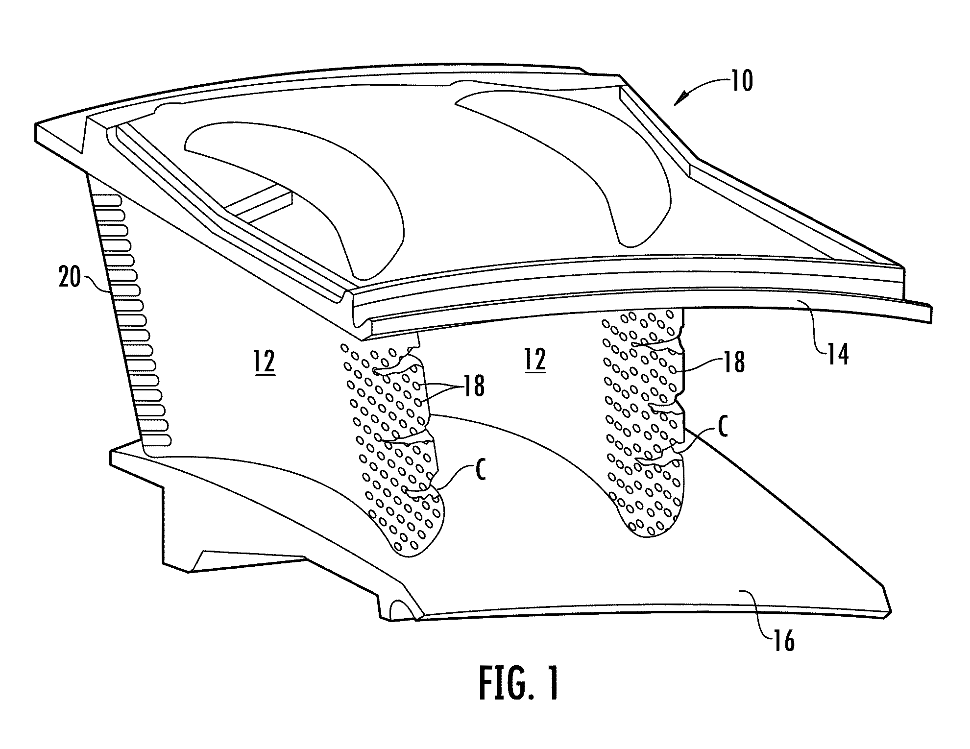
[0018]Referring to the drawings wherein identical reference numerals denote the same elements throughout the various views, FIG. 1 illustrates an exemplary turbine nozzle segment 10. A gas turbine engine will include a plurality of such segments 10 arranged in an annular array. The turbine nozzle segment 10 is merely an example of a coated metallic turbine component, and the repair methods described herein are equally applicable to other components, nonlimiting examples of which include combustor liners, rotating turbine blades, and turbine shrouds.

[0019]The turbine nozzle 10 includes first and second nozzle vanes 12 disposed between an arcuate outer band 14 and an arcuate inner band 16. The vanes 12 define airfoils configured so as to optimally direct the combustion gases to a turbine rotor (not shown) located downstream thereof. The outer and inner bands 14 and 16 define the outer and inner radial boundaries, respectively, of the gas flow through the nozzle segment 10. The interio...


PUM

PropertyMeasurementUnit
thicknessaaaaaaaaaa
thickaaaaaaaaaa
air pressureaaaaaaaaaa

Abstract

A method is provided for repairing a metallic turbine component which includes a thermal barrier coating system including a metallic bond coat and a ceramic top coat. The method includes: (a) removing the top coat using a mechanical process; (b) partially stripping the metallic bond coat from the component, such that substantially no material of the component is removed; (c) repairing at least one defect in the turbine component; (d) applying a new metallic bond coat to the turbine component; and (e) applying a new ceramic top coat over the metallic bond coat.

Description

BACKGROUND OF THE INVENTION[0001]This invention relates generally to the repair of gas turbine engine components and more particularly to the repair of turbine components incorporating ceramic thermal barrier coatings.[0002]Gas turbine engines include a “hot section” comprising a combustor and one or more downstream turbines. Components in the hot section are exposed during operation to a high temperature, corrosive gas stream that limits their effective service life. Accordingly, these components are typically fabricated from high temperature cobalt or nickel-based “superalloys” and are often coated with corrosion and / or heat resistant materials, and in particular with ceramic thermal barrier coatings (TBCs).[0003]Examples of such components include but are not limited to high pressure turbine blades and nozzles, and turbine blade shrouds. Despite the use of protective coatings, such components commonly develop defects such as cracks, damage, or material loss during service.[0004]T...

Claims


Application Information

Patent Timeline
Patent Type & Authority Applications(United States)
IPC IPC(8): B23P6/04
CPCB23P6/007B23P6/045C23C4/02C23C4/04F01D5/005Y10T29/49318C23C28/3215C23C28/325C23C28/3455F05D2230/90C23C28/321
Inventor GUPTA, BHUPENDRA KUMARGRADY, WAYNE RAYGARCIA, ANTOINE FREITAS
Owner GENERAL ELECTRIC CO
Why Eureka
Try Eureka