Electric power generating turbine engine fuel supply system

a technology for turbine engines and fuel supply systems, applied in the direction of engine starters, electric generator control, machines/engines, etc., can solve the problems of increasing the weight and cost excessive heat of the overall fuel system, and affecting the overall fuel system design

Active Publication Date: 2010-05-27
HONEYWELL INT INC
View PDF11 Cites 40 Cited by
  • Summary
  • Abstract
  • Description
  • Claims
  • Application Information

AI Technical Summary

Problems solved by technology

As a result, the overall fuel system design may exhibit certain undesirable drawbacks.
For example, a relatively larger electric pump may generate excessive fuel system heat, and / or may increase overall fuel system weight and costs.

Method used


Image

  • Electric power generating turbine engine fuel supply system
  • Electric power generating turbine engine fuel supply system

Examples


Embodiment Construction

[0011]The following detailed description is merely exemplary in nature and is not intended to limit the invention or the application and uses of the invention. Furthermore, there is no intention to be bound by any theory presented in the preceding background or the following detailed description. In this regard, although an embodiment of the invention is described as being implemented in an aircraft and for a gas turbine engine, it will be appreciated that the invention may be implemented in numerous and varied end-use environments where fuel flow to primary and secondary fuel loads is controlled.

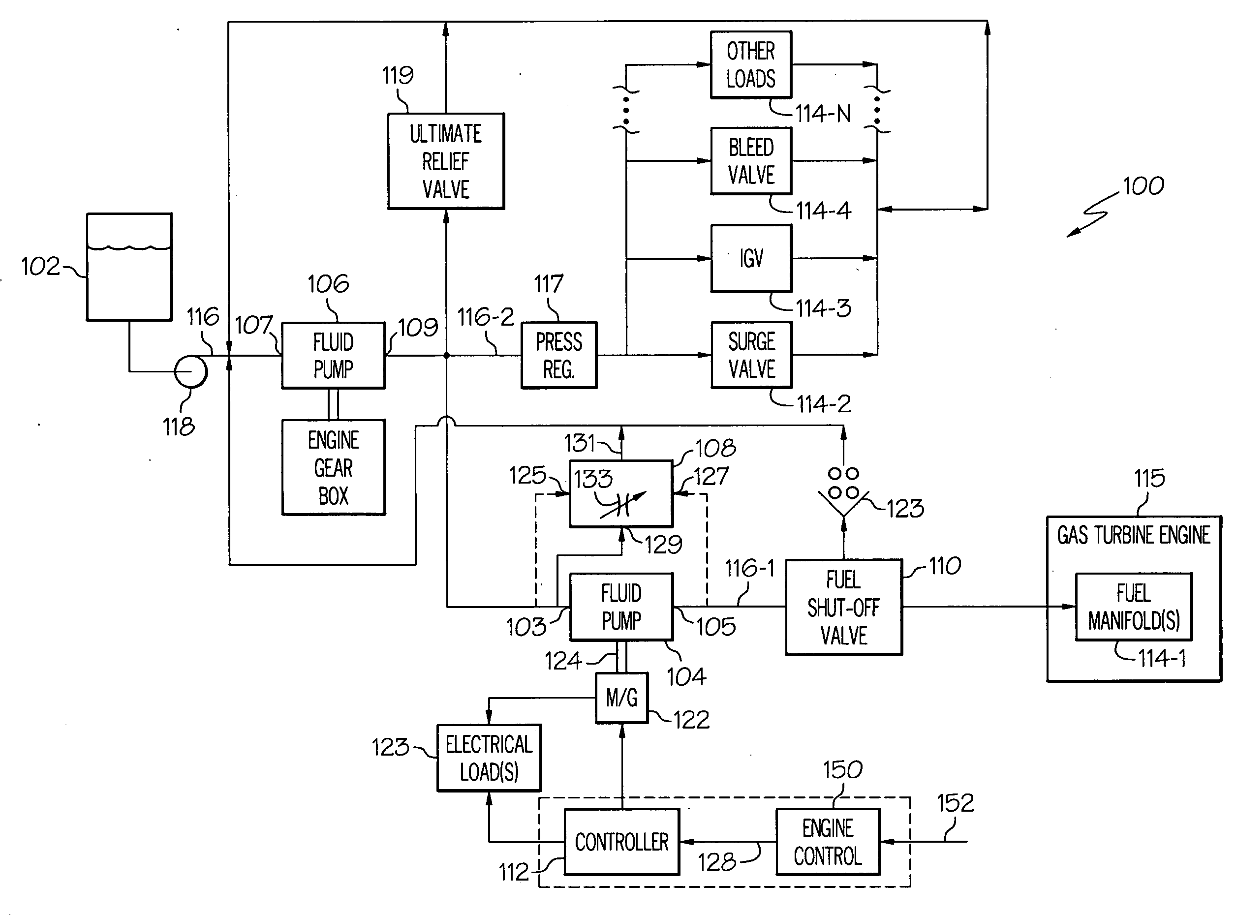
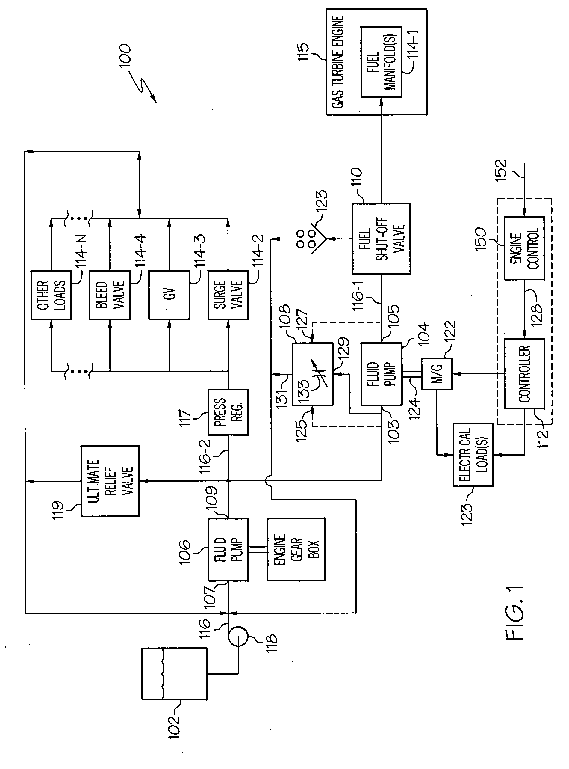
[0012]Turning now to FIG. 1, a simplified schematic diagram of one embodiment of a fuel delivery and control system for a gas turbine engine, such as a turbofan jet aircraft engine, is depicted. The system 100 includes a fuel source 102, a fluid-powered metering pump 104, a mechanically-driven fuel pump 106, a metering pump differential pressure control valve 108, a fuel shut-off valve 110,...


PUM


Abstract

A turbine engine fuel supply system includes a priority flow line, a plurality of secondary fuel loads, a fluid-powered metering pump, a mechanically-driven fuel pump, and an electric machine. The fluid-powered metering pump, upon receiving fuel at its fuel inlet, rotates at a rotational speed, discharges the fuel from its fuel outlet at a flow rate dependent on the rotational speed, and supplies a first drive torque. The mechanically-driven fuel pump receives a second drive torque and, in response, draws fuel into its fuel inlet and discharges the fuel from its outlet to the fluid-powered metering pump fuel inlet to drive the fluid-powered metering fuel pump. The electric machine receives the first drive torque from the fluid-powered metering pump and generates electrical power.

Description

TECHNICAL FIELD[0001]The present invention generally relates to turbine engine fuel supply systems and, more particularly, to a turbine engine fuel supply system that is configured with a pump driven generator that at least selectively generates electrical power.BACKGROUND[0002]Typical gas turbine engine fuel supply systems include a fuel source, such as a fuel tank, and one or more pumps. The one or more pumps draw fuel from the fuel tank and deliver pressurized fuel to one or more primary fuel loads and to one or more secondary fuel loads via one or more supply lines. Generally, the primary fuel loads, which include the fuel manifolds in the engine combustor, are supplied with fuel via, for example, a priority flow line. The secondary fuel loads, which may include a motive flow valve and regulator, one or more variable geometry actuators, and one or more bleed valves, are supplied with fuel via, for example, a secondary flow line.[0003]Recently, there has been a desire to implemen...

Claims


Application Information

Patent Timeline
Patent Type & Authority Applications(United States)
IPC IPC(8): F02C9/30F02C7/22F02C6/00
CPCF02C7/22F02C7/236F05D2220/762F05D2260/406F02C9/30
Inventor ANSON, BRUCE
Owner HONEYWELL INT INC
Why Eureka
Try Eureka