

Inertia force sensor
a sensor and inertial force technology, applied in the direction of acceleration measurement using interia force, turn-sensitive devices, instruments, etc., can solve the problem of reducing detection accuracy and achieve the effect of high sensitivity
- Summary
- Abstract
- Description
- Claims
- Application Information
AI Technical Summary
Benefits of technology
Problems solved by technology
Method used
Image

Examples
exemplary embodiment 1
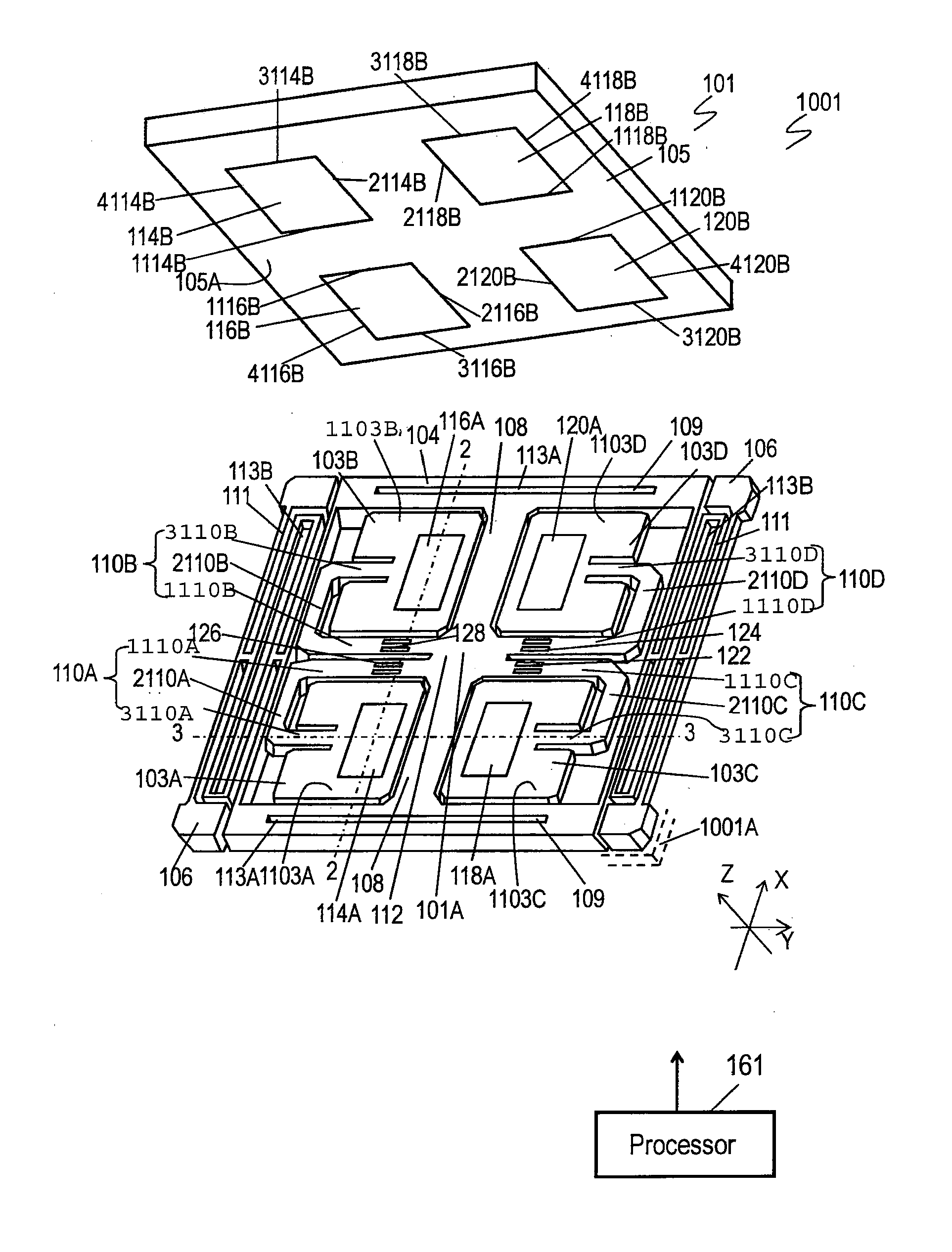
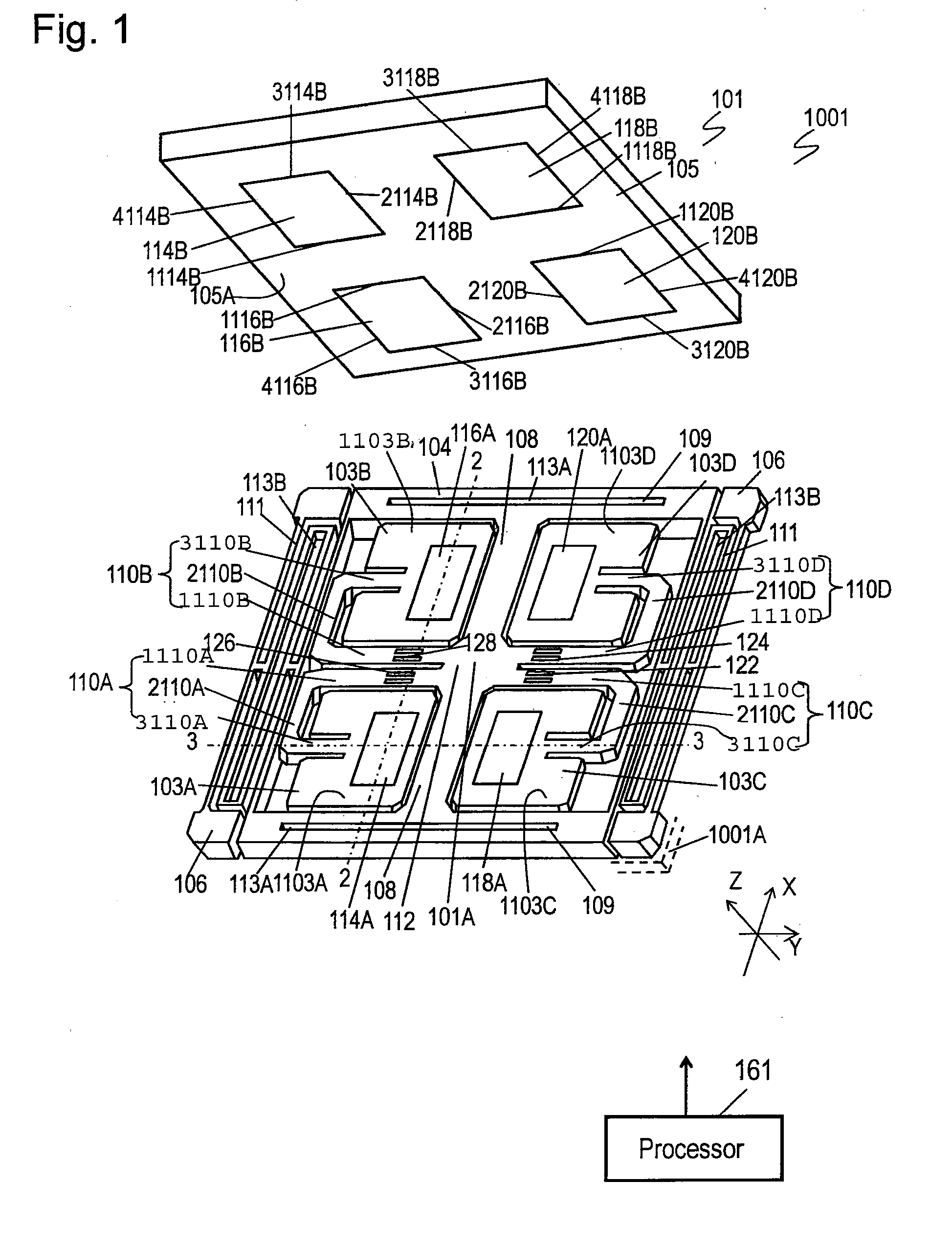
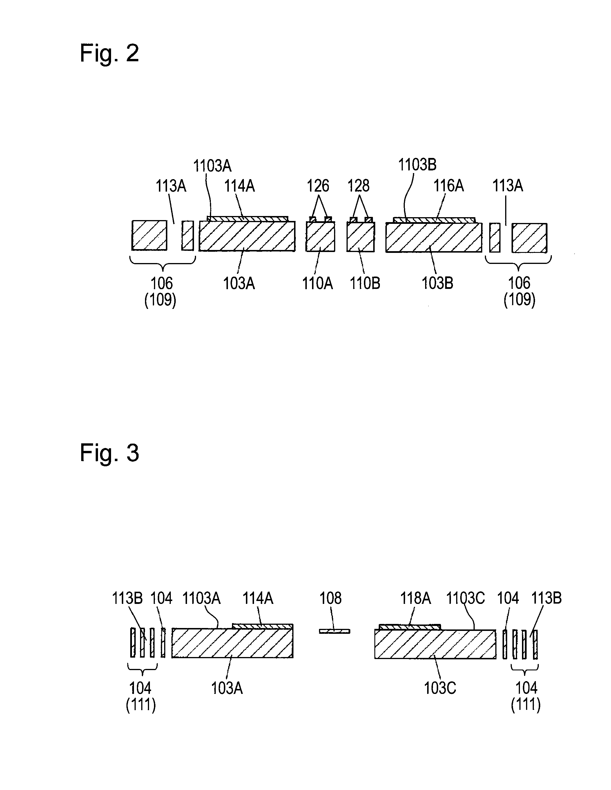
[0169]FIG. 1 is an exploded perspective view of sensor element 101 of inertial force sensor 1001 according to Exemplary Embodiment 1 of the present invention. FIGS. 2 and 3 are sectional views of sensor element 101 on line 2-2 and line 3-3 shown in FIG. 1, respectively. Inertial force sensor 1001 can detect an acceleration and an angular velocity.
[0170]A Z-axis, an X-axis, and a Y-axis, a first axis, a second axis, and a third axis, perpendicular to each other are defined as shown in FIG. 1. Two arms 108 extend from supporter 112 along the X-axis and are connected to fixing portion 104 having a frame shape. Supporter 112 is joined to fixing portion 104 via arms 108. Arms 108 extend perpendicularly to fixing portion 104. Four arms 110A to 110D extend from supporter 112 along the Y-axis and are connected to four weights 103A to 103D, respectively. Arms 108 and 110A to 110D are flexible and constitute a flexible portion together with supporter 112. The flexible portion is connected to ...
exemplary embodiment 2
[0193]FIG. 9A is an exploded perspective view of sensor element 201 of inertial force sensor 1002 according to Exemplary Embodiment 2 of the present invention. FIG. 9B is a perspective view of sensor element 201. FIGS. 10 and 11 are sectional views of sensor element 201 on line 10-10 and line 11-11 shown in FIG. 9A, respectively. Inertial force sensor 1002 can detect an acceleration and an angular velocity.
[0194]A Z-axis, the X-axis, and the Y-axis, a first axis, a second axis, and a third axis perpendicular to each other, are defined as shown in FIGS. 9A and 9B. Two arms 208 extend from supporter 212 along the X-axis and connected to fixing portion 204 having a frame. Supporter 212 is joined to fixing portion 204 via arms 208. Arms 208 extend perpendicular to fixing portion 204. Four arms 210A to 210D extend from supporter 212 along the Y-axis and are connected to four weights 203A to 203D, respectively. Arms 208 and 210A to 210D are flexible and constitute a flexible portion toget...
exemplary embodiment 3
[0217]FIG. 16A is an exploded perspective view of sensor element 301 of inertial force sensor 1003 according to Exemplary Embodiment 3 of the present invention. FIG. 16B is a perspective view of sensor element 301. FIGS. 17 and 18 are sectional views of sensor element 301 on line 17-17 and line 18-18 shown in FIG. 16A, respectively. Inertial force sensor 1003 can detect an acceleration and an angular velocity.
[0218]A Z-axis, an X-axis, and a Y-axis, a first axis, a second axis, and a third axis perpendicular to each other are defined as shown in FIGS. 16A and 16B. Two arms 308 extend from supporter 312 along the X-axis and are connected to fixing portion 304 having a frame shape. Supporter 312 is joined to fixing portion 304 via arms 308. Arms 308 extend perpendicularly to fixing portion 304. Four arms 310A to 310D extend from supporter 312 along the Y-axis and are connected to four weights 303A to 303D, respectively.
[0219]Arms 308 and 310A to 310D and supporter 312 are flexible and...
PUM
 Abstract
Description
Claims
Application Information