
Suspension device for containers

Inactive Publication Date: 2010-05-27
BRASILATA S A EMBALAGENS METALICAS
View PDF13 Cites 10 Cited by
  • Summary
  • Abstract
  • Description
  • Claims
  • Application Information

AI Technical Summary

Benefits of technology

[0007]As a function of said drawbacks of the known solutions, in order to provide a suspension device in cans or other containers of the type which comprises an annular upper wall defining, in its inner edge, a closing seat in which is seated and retained a lid, it is an object of the present invention to provide the tubular body of the container with a suspension device, without requiring operations of welding suspension elements to the tubular body.
[0008]It is a further object of the present invention to provide a suspension device for said containers, which can be easily applied to the tubular body of the container, before or after the product filling and before or after closing the lid.
[0011]It is also another object of the present invention to provide a suspension device as mentioned above, which can be associated with a lid to be removed and reclosed several times, by means of simple operations which do not require the use of tools to help opening the lid.
[0014]The above-defined suspension device complies with one of the objects of the invention, allowing a container, generally in the form of a cylindrical can, to be easily provided with a retaining ring that is simply fitted over the outer peripheral projection of the upper edge of the tubular body of the container and which remains securely and axially retained to the latter, in order to allow the container to be suspended by the handle incorporated in a single piece to the retaining ring.
[0015]The construction proposed by the invention allows the retaining ring to be mounted around the tubular body at any time, even after the filling, and the closure of the lid, when the latter does not interact with the retaining ring.

Problems solved by technology

These cans, dimensioned to contain an amount of product which makes them heavy and of difficult portability, generally require the provision of a suspension device which usually takes the form of a handle in metallic wire, with the ends hingedly retained in respective ears externally affixed to the side wall of the tubular body.
These drawbacks increase the cost of the package.
Besides considerably increasing the cost of the package, said prior art suspension device requires the fixation of the ears to the tubular body and the final mounting of the wire handle to be compulsorily carried out by the package manufacturer, before filling the can with the product to be stored.
Thus, the cans or other similar containers are sent to the filling phase already provided with the lateral ears and the wire handle, which parts project outwardly from the contour of the container, interfering with other containers disposed side by side during shipping and storage operations, increasing the area occupied by said containers and permitting the occurrence of damage, in higher or lower degree, to the side wall finishing of these containers.
Another aspect to be associated with said known solutions is the fact 4 that said suspension devices have only the suspension function, which does not help to improve the relative transversal interlocking between two containers stacked one on top of the other or, optionally, to interact with the container lid, so as to provide, with said lid, a tamper evident seal.

Method used


Image

  • Suspension device for containers
  • Suspension device for containers
  • Suspension device for containers

Examples


Embodiment Construction

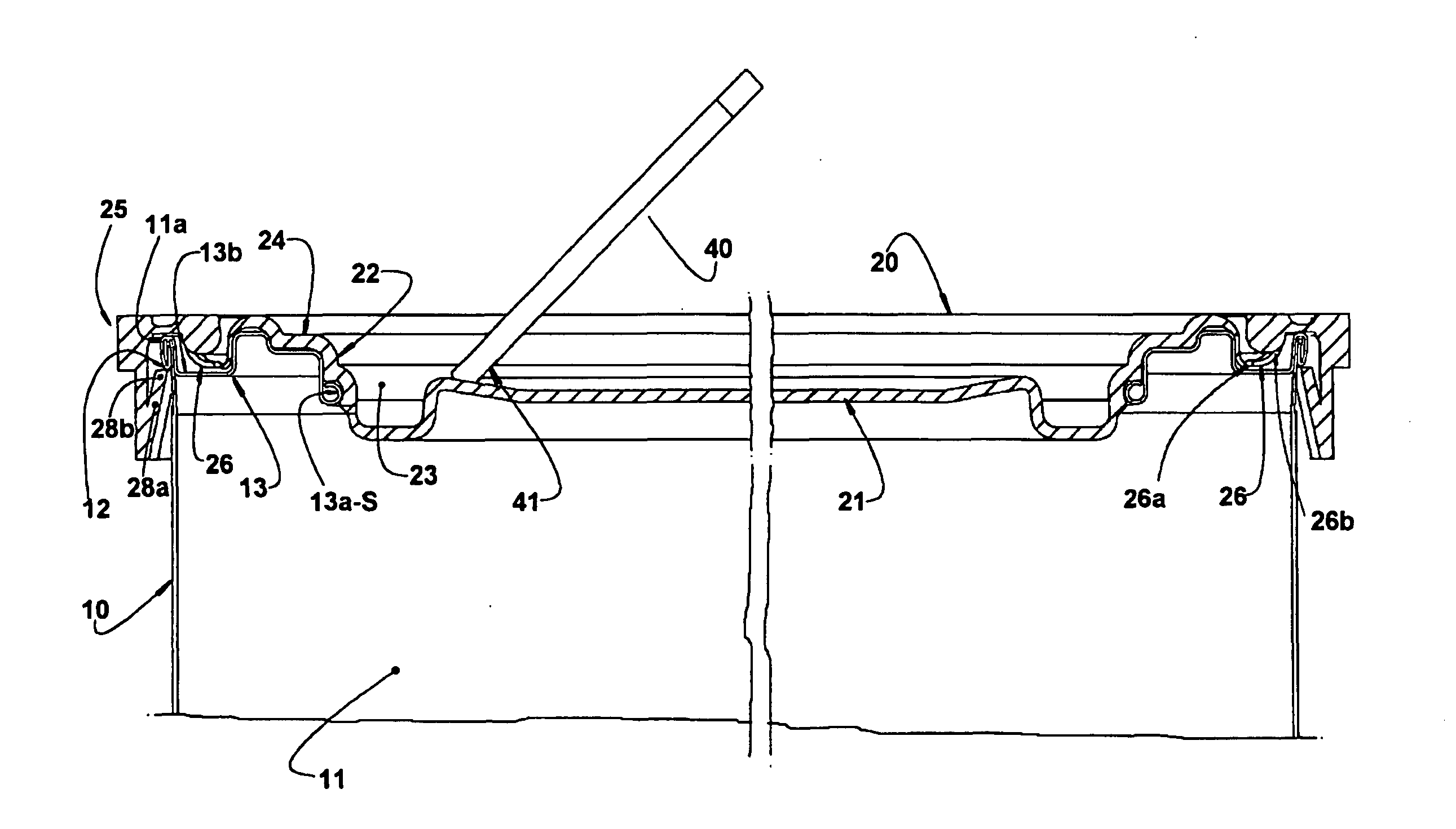
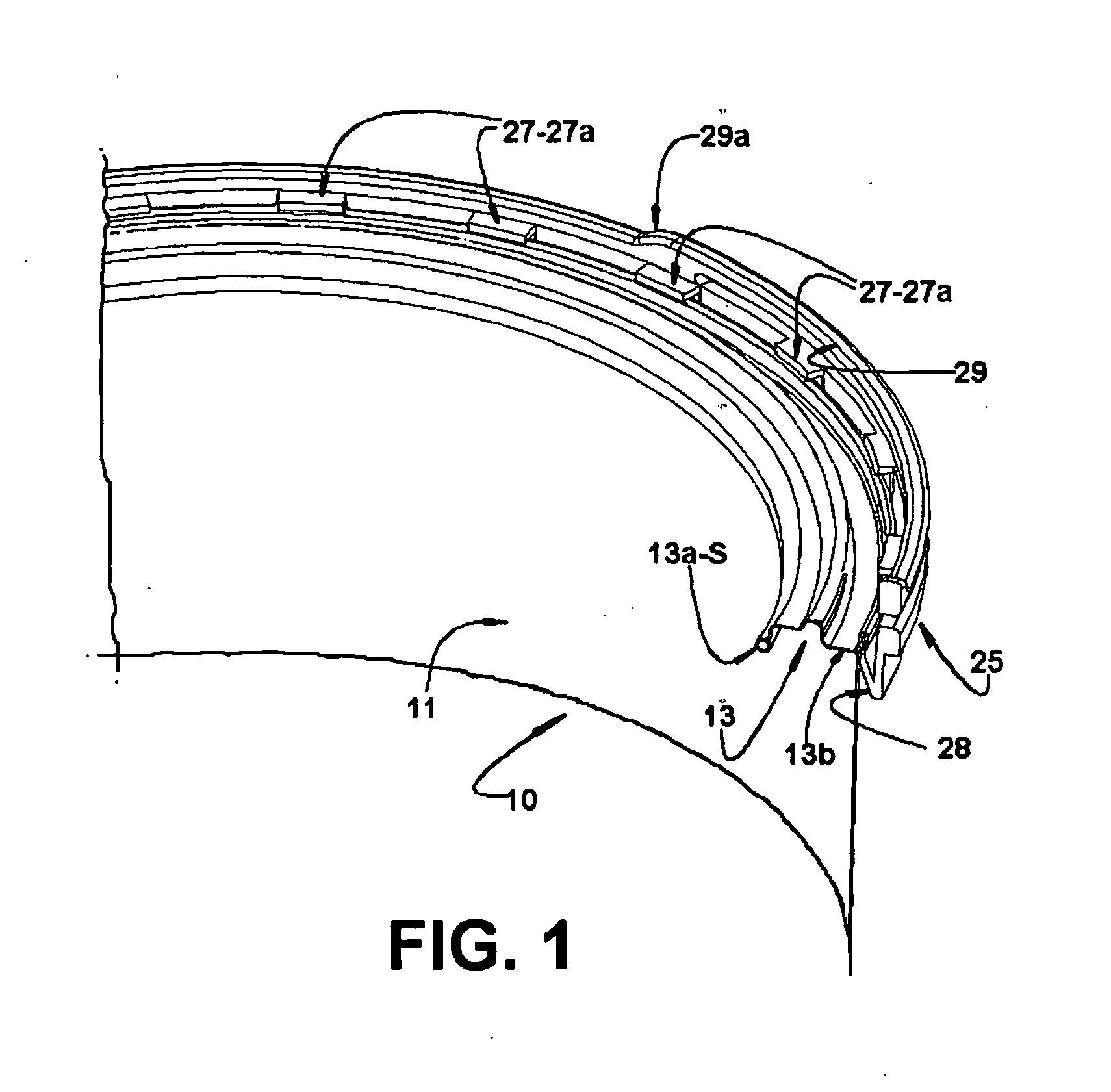
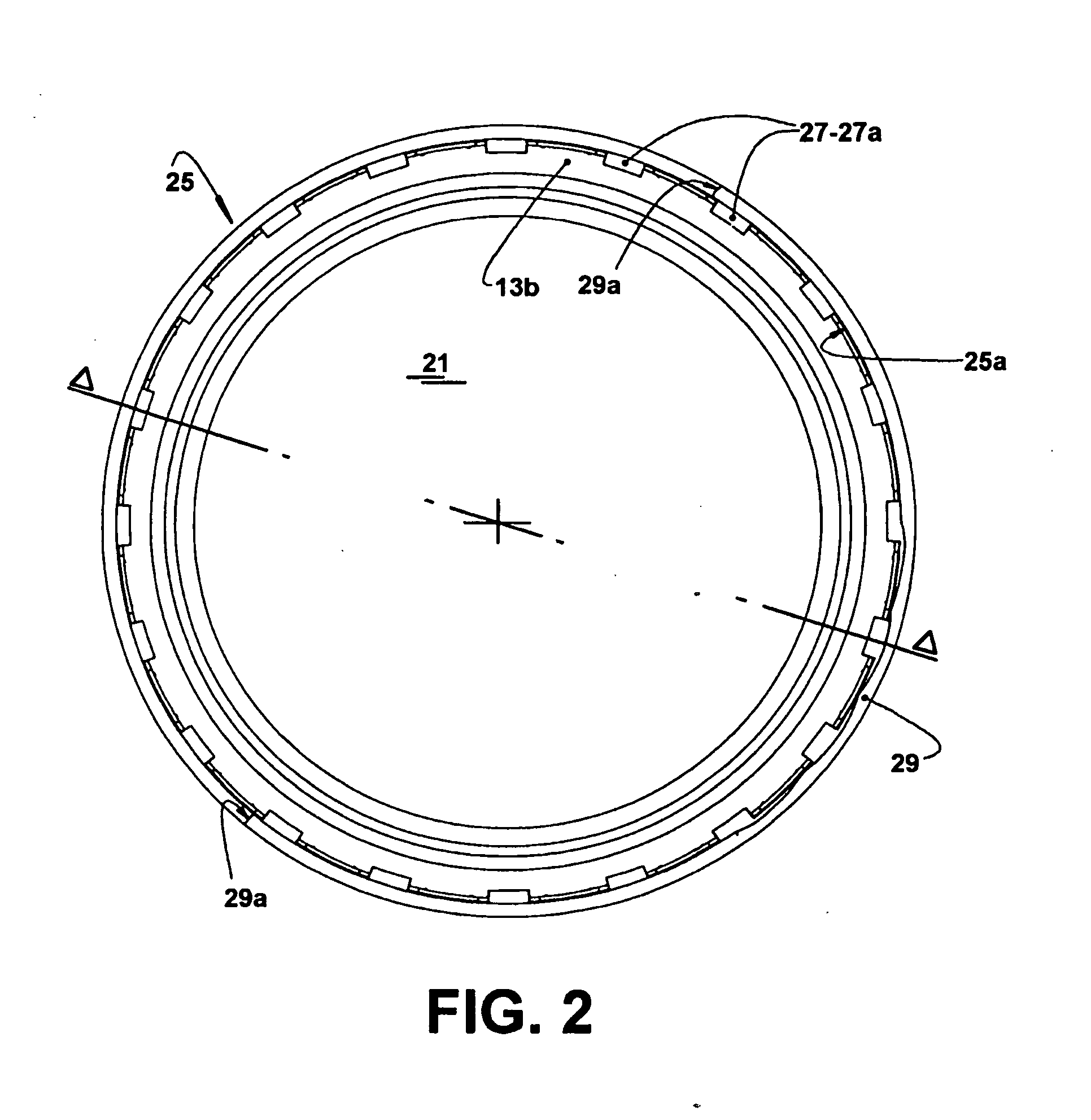
[0031]As illustrated in the enclosed drawings, the present suspension device is applied to a container, generally a can, of the type which comprises a tubular body 10, formed in metal sheet, inferiorly closed by a bottom wall and having a side wall 11 provided with an upper edge 11a which incorporates an outer peripheral projection 12, said tubular body 10 carrying an annular upper wall 13 having an inner edge 13a that is bent to form a closing seat “S” which, in the illustrated constructions, takes the form of a convex arc.

[0032]According to FIGS. 1-11, the annular upper wall 13 presents a peripheral portion 13b which is double-seamed in the upper edge 11a of the side wall 11 of the tubular body 10 of the container, said double-seaming being responsible for forming the outer peripheral projection 12.

[0033]Further according to the construction illustrated in FIGS. 1-11, the annular upper wall 13 has its upwardly and radially outwardly bent inner edge 13a defining a tubular rib 14, i...


PUM


Abstract

A suspension device is applied to containers comprising a tubular body (10) having a side wall (11) carrying an outer peripheral projection (12) and an annular upper wall (13). The device comprises a retaining ring (25) incorporating an inner radial flange (27) to be seated onto an upper edge (11a) of the tubular body (10), and elastically deformed retaining fingers (28) that are fitted under and against the outer peripheral projection (12), in the condition in which the retaining ring (25) is mounted around the tubular body (10) and axially retained under said outer peripheral projection (12), said retaining ring (25) affixing end portions (29a) of a suspension handle (29), that is displaced between a rest position and a raised operative position.

Description

FIELD OF THE INVENTION [0001]The present invention refers to a suspension device to be applied in the closing of metallic cans or other containers defined by a tubular body with a generally cylindrical side wall of constant or variable diameter. Said tubular body is inferiorly closed by a bottom wall and carries an annular upper wall having an inner edge which defines an upper opening for the container and which is configured to form a closing seat on which is removably seated and axially retained a lid made of plastic or metallic material or any other material compatible with the product to be stored in the container.PRIOR ART [0002]There are well known from the prior art the containers in the form of a cylindrical can such as, for example, the one-gallon cans utilized to store paints, varnishes and other bulk products, usually of progressive consumption. These cans, dimensioned to contain an amount of product which makes them heavy and of difficult portability, generally require t...

Claims


Application Information

Patent Timeline
IPC IPC(8): B65D90/02
CPCB65D25/32B65D43/021B65D2525/284B65D2525/288B65D2543/00296B65D2543/00435B65D2543/00851B65D2543/00546B65D2543/00638B65D2543/00685B65D2543/0074B65D2543/00796B65D2543/00509
Inventor ALVARES, ANTONIO CARLOS TEIXEIRADA CUNHA, SILVERIO CANDIDO
Owner BRASILATA S A EMBALAGENS METALICAS
Learn More