Systems and Methods for Using a Power Converter for Transmission of Data over the Power Feed

a power converter and power feed technology, applied in the field of photovoltaic systems, can solve the problems of limited signal rate that can be carrier by a frequency, method requires additional hardware, and the amount and nature of noise sources are difficult to predi

Active Publication Date: 2010-05-27
NEWLIGHT CAPITAL LLC
View PDF81 Cites 206 Cited by
  • Summary
  • Abstract
  • Description
  • Claims
  • Application Information

AI Technical Summary

Problems solved by technology

However, these systems and methods require additional hardware for the transmission and reception of data in a solar panel system.
Many of the issues involved in sending communication signals over DC power lines also exist when sending such signals over the AC power grid.
The properties of the transmission medium vary greatly, and the amount and nature of noise sources are very difficult to predict.
Hence, a majority of sources and loads on a DC bus employ electronic DC-DC converters, which are very strong noise emitters.
There are many challenges to communicating digital data quickly and reliably over a set of wires intended to conduct electrical energy.
The signal rate that can be carrier by a frequency is also limited by severe noise and attenuation typical to power lines.
Broadband communication products deliver local area network performance but can not handle more than just a handful of nodes on the network.
Such products lack the robustness and reliability that is needed for a sensor network.
That limitation inhibits them from installing more solar panel modules, often referred to as “modules” or “panels,” in series to reduce the cost of combiner boxes or string inverters.
When solar modules are connected in series or in mesh configurations, there can be a problem in which weaker modules not only produce less energy but also affect other modules' capabilities to deliver energy in the same string or wiring section.

Method used


Image

  • Systems and Methods for Using a Power Converter for Transmission of Data over the Power Feed
  • Systems and Methods for Using a Power Converter for Transmission of Data over the Power Feed
  • Systems and Methods for Using a Power Converter for Transmission of Data over the Power Feed

Examples


Embodiment Construction

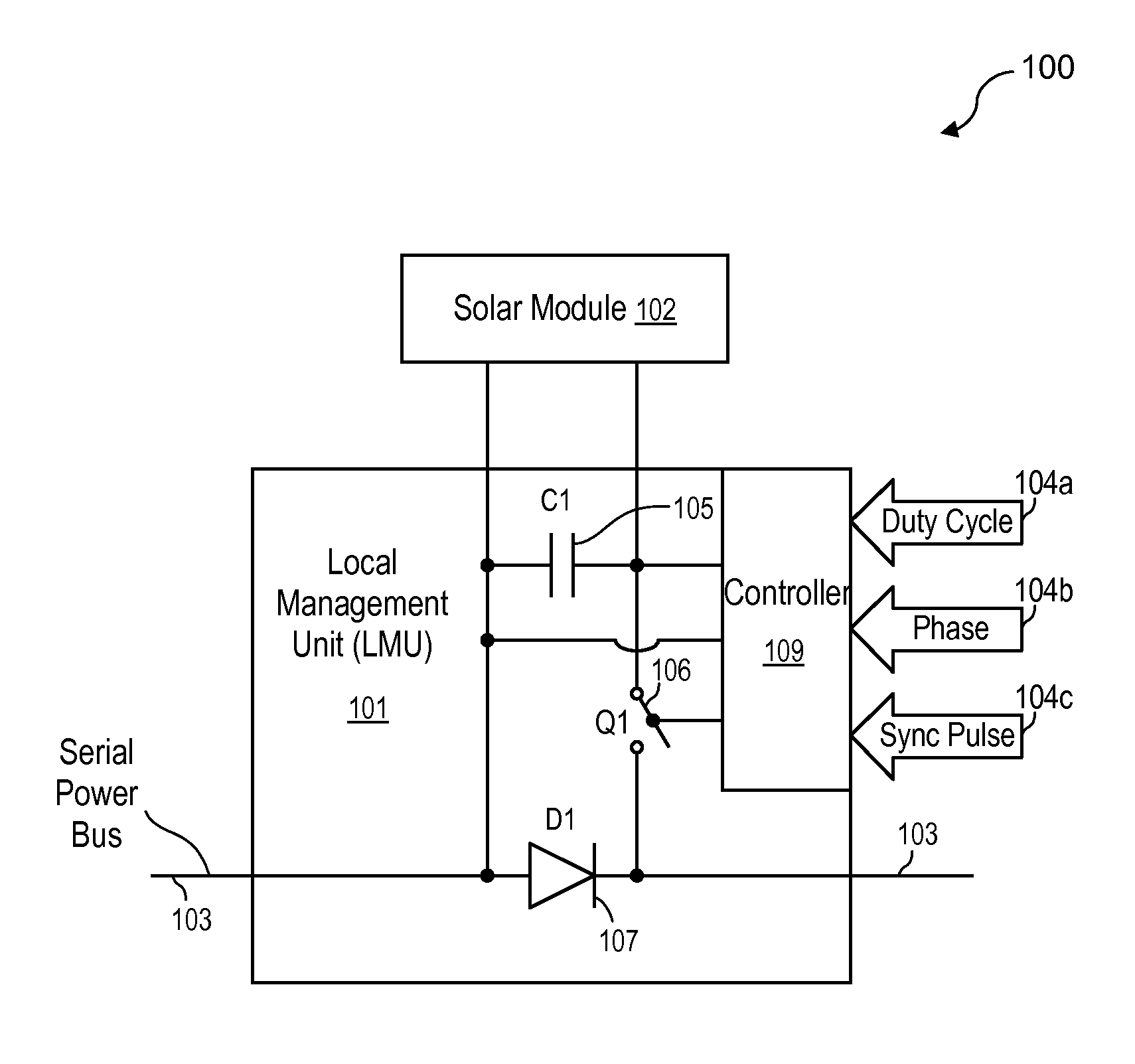
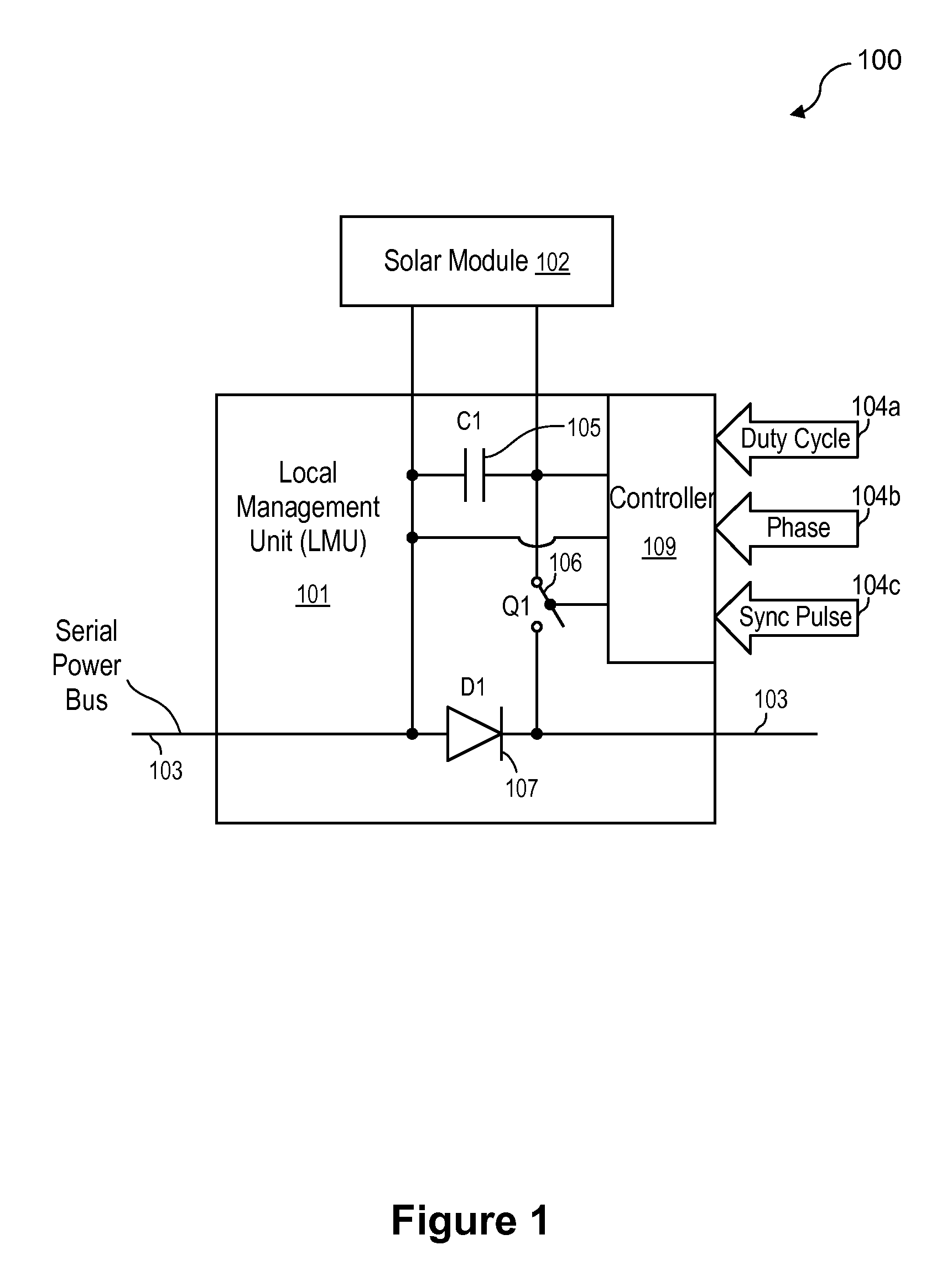
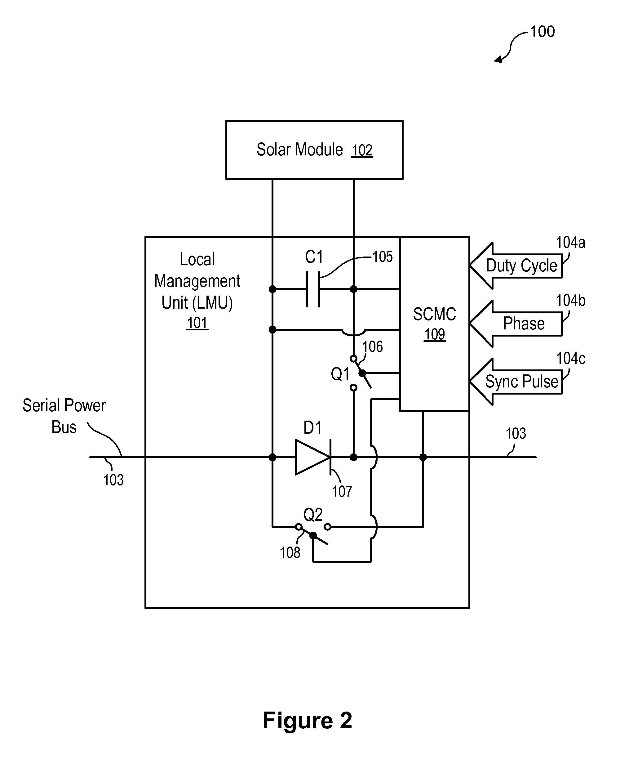
[0027]The following description and drawings are illustrative and are not to be construed as limiting. Numerous specific details are described to provide a thorough understanding. However, in certain instances, well known or conventional details are not described in order to avoid obscuring the description. References to one or an embodiment in the present disclosure are not necessarily references to the same embodiment; and, such references mean at least one.

[0028]When solar modules are connected in series or mesh configuration, there can be a problem in which weaker modules not only produce less energy but also affect other modules in the same string or wiring section. By measuring one can determine that a few modules are weaker than the others in most commercially installed strings. Thus, the string is generating less power than the sum available at each module if modules were operated separately.

[0029]At least one embodiment of the present disclosure provides methods and systems...


PUM


Abstract

Apparatuses and methods include a photovoltaic energy production unit to generate electricity. A local management unit is coupled between the photovoltaic energy production unit and a connection of energy production units forming a string bus. The local management unit includes a controller and switching circuitry. The controller provide a control for the switching circuitry to deliver electrical energy to the string bus. A communication transmission modulator is associated with the local management unit. The communication transmission modulator modulates the control with data to be transmitted from the local management unit over the string bus.

Description

CROSS-REFERENCE TO RELATED APPLICATIONS[0001]The present application is a continuation-in-part of U.S. patent application Ser. No. 12 / 411,317, filed Mar. 25, 2009, which claims the benefit of Provisional U.S. Application Ser. No. 61 / 200,601, filed Dec. 2, 2008 and Provisional U.S. Application Ser. No. 61 / 200,279, filed Nov. 26, 2008. The present application also claims the benefit of Provisional U.S. Application Ser. No. 61 / 207,296, filed Feb. 10, 2009. The disclosures of the above-mentioned applications are hereby incorporated herein by reference.FIELD OF THE TECHNOLOGY[0002]At least some embodiments of the disclosure relate to photovoltaic systems in general, and more particularly but not limited to, improving the energy production performance of photovoltaic systems.BACKGROUND[0003]Conventional systems for transmission of data over low impedance power feed lines exist. However, these systems and methods require additional hardware for the transmission and reception of data in a s...

Claims


Application Information

Patent Timeline
Patent Type & Authority Applications(United States)
IPC IPC(8): H02J1/00G05B11/01
CPCH02J13/0003H02M3/28H04B3/548Y02E40/72Y02E10/563Y04S10/123H02J3/383H04B2203/5458H02J2300/24H02J3/381Y02E10/56Y02E40/70H02J13/00016
Inventor HADAR, RONARDITI, SHMUELAVRUTSKY, MORDECHAY
Owner NEWLIGHT CAPITAL LLC
Why Eureka
Try Eureka