Method for detecting the diameter of a single crystal and single crystal pulling apparatus

a technology of pulling apparatus and diameter, which is applied in the direction of chemistry apparatus and processes, instruments, crystal growth process, etc., can solve the problems of affecting the accuracy of measurement. , to achieve the effect of improving the measurement accuracy of the diameter of a large-diameter, enhancing yield, and reducing quality variation

Active Publication Date: 2010-05-27
SHIN-ETSU HANDOTAI CO LTD
View PDF4 Cites 7 Cited by
  • Summary
  • Abstract
  • Description
  • Claims
  • Application Information

AI Technical Summary

Benefits of technology

[0023]As described above, in the single crystal pulling apparatus including both a camera and a load cell, by detecting the diameter of a single crystal by the single crystal diameter detection method of the invention, it is possible to utilize the advantages of a camera method and a load cell method and can make up for the disadvantages thereof, improve the measurement accuracy of the diameter of a large-diameter, heavy crystal more effectively, and achieve th...

Problems solved by technology

However, too large a diameter increases grinding/polishing stock removal, making it uneconomical.
However, with the method for measuring the ends of a crystal by a camera, it becomes difficult to capture a diameter D shown in FIG. 1 in its entirety as the diameter of the crystal increases.
Moreover, the problem is that, even when the diameter is captured in its entirety, degradation in resolution occurs.
However, in this case, an error caused by displacement of the relative positions of the cameras becomes a problem.
However, a measurement error occurs due to displacement of the virtual point caused by displacement of the position of a camera.
However, the problem of this method is that the curvature becomes small as the diameter of a crystal increases, resulting in an increase in measurement error.
As described above, the problem of the single crystal diameter detection method using the optical method is that a measurement error occurs due to an increase in diameter of a crystal or displacement of a camera for detection.
For example, when the crystal diameter deviates from a target, a problem arises, such as a reduction in yields du...

Method used


Image

  • Method for detecting the diameter of a single crystal and single crystal pulling apparatus
  • Method for detecting the diameter of a single crystal and single crystal pulling apparatus
  • Method for detecting the diameter of a single crystal and single crystal pulling apparatus

Examples


example 1

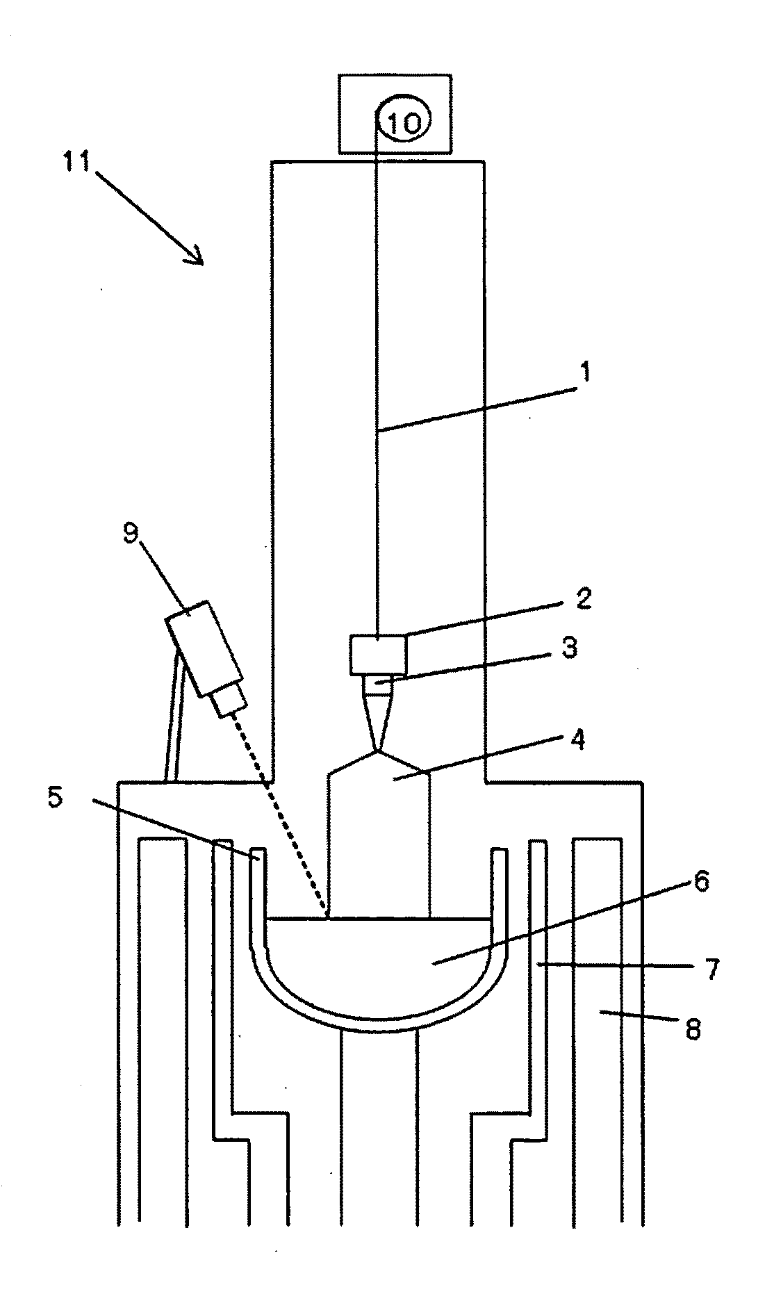
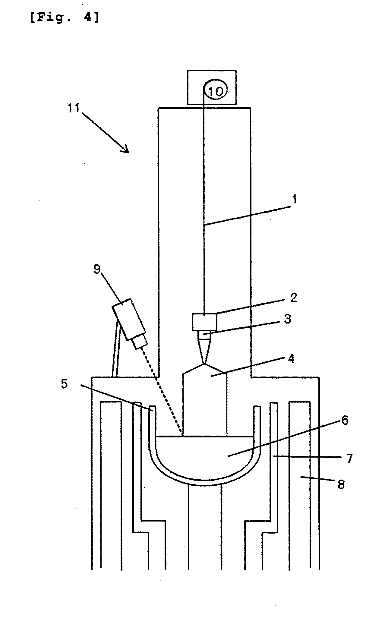
[0056]A single crystal was produced by using the single crystal pulling apparatus of FIG. 4, performing correction of a diameter detected by the camera by a method according to the flow shown in FIG. 5, and controlling the diameter so as to be a value obtained by the correction. Before production of the single crystal, a relationship between a growth rate and a correction coefficient in a single crystal pulling apparatus to be actually used was obtained in advance (FIG. 7). By setting the length L1 of a straight body at the start of calculation to 5 cm and setting the length L2 of the straight body to 15 cm, a diameter Do detected by the camera between 5 cm and 15 cm and a diameter Dw determined based on the amount of change in weight between 5 cm and 15 cm were detected. After the straight body became 15 cm, correction of the diameter detected by the camera was performed by adding, to the diameter detected by the camera, a value obtained by adding a correction coefficient −1.5 corr...

example 2

[0057]A single crystal was produced by using the same single crystal pulling apparatus as that used in Example 1 by a method similar to that in Example 1, except that the length L1 of a straight body at the start of calculation was set to 5 cm, the length L2 of the straight body was set to 25 cm, and the average interval in which correction was calculated was set to 20 cm, by performing correction of a diameter detected by the camera by adding, to the diameter detected by the camera, a value obtained by addition of a correction coefficient −1.5 corresponding to an actual pulling rate 0.4 mm / min, and controlling the diameter of a single crystal so as to be a value obtained by the correction. As in Example 1, the diameter after production of the crystal was measured in a 40 cm part of the straight body, and diameter variation (standard deviation σ) was evaluated.

example 3

[0062]A single crystal was produced by using the same single crystal pulling apparatus as that in Example 1, setting the average interval (L2−L1) in which correction was calculated to 5 cm, 10 cm, 15 cm, and 20 cm, and controlling the diameter of a single crystal by a method similar to that in Example 1, and a diameter calculation error of the load cell in a 40 cm part of a straight body was examined. The results revealed that an actual error in the weights repeatedly measured by the load cell was 100 g in any of the 5 cm to 20 cm average intervals (L2−L1), and a diameter conversion error in an interval of 10 cm or more was approximately 1 mm or less.

[0063]FIG. 10 is a graph showing the relationship between the average interval (L2−L1) in which correction is calculated and a diameter calculation error of a load cell, the relationship observed in Example 3. It is clear from FIG. 10 that there is not a great difference between the 10 cm average interval (L2−L1) and the 20 cm average i...


PUM


Abstract

The invention is a method for detecting the diameter of a single crystal grown by the Czochralski method, wherein the diameter of a single crystal is detected by both a camera and a load cell, the diameter detected by the camera is corrected based on a difference between the diameter detected by the camera and the diameter calculated by the load cell and a correction coefficient α obtained in advance according to a growth rate of the single crystal, and a value obtained by the correction is set as the diameter of the single crystal, and a single crystal pulling apparatus including both a camera and a load cell for detecting the diameter of a single crystal to be pulled upwardly. As a result, it is possible to improve the measurement accuracy of the diameter of a large-diameter, heavy crystal and achieve the enhancement of yields and a reduction in variations in quality.

Description

TECHNICAL FIELD[0001]The present invention relates to a method for detecting the diameter of a single crystal grown by the Czochralski method and a single crystal pulling apparatus.BACKGROUND ART[0002]As a semiconductor silicon single-crystal growth method, the Czochralski method (hereinafter, the CZ method) is known. In this method, a seed crystal is immersed in a melt and is slowly pulled upwardly while being rotated, whereby a single crystal is grown. The single crystal is produced so as to have a certain diameter. For example, when a finished product is an 8 inch (200 mm) wafer, it is common to produce a crystal having a diameter of 200 to 210 mm, which is slightly greater than the diameter of the wafer. Then, the crystal is ground at the outer circumference thereof so as to have a cylindrical shape, and is sliced into wafers. The wafer is then subjected to chamfering, and has an ultimate target wafer diameter. The target diameter in the production of a single crystal has to be ...

Claims


Application Information

Patent Timeline
IPC IPC(8): G01N21/00C30B15/26
CPCC30B15/26Y10T117/1004C30B15/28
Inventor YANAGIMACHI, TAKAHIROSONOKAWA, SUSUMU
Owner SHIN-ETSU HANDOTAI CO LTD
Why Eureka
Try Eureka