

Ozone-less static eliminator
a static eliminator, ozone-less technology, applied in the direction of electrographic process equipment, instruments, corona discharge, etc., can solve the problems of environmental contamination caused by other flotage diverging or discharged from the case, hardening and deteriorating,
- Summary
- Abstract
- Description
- Claims
- Application Information
AI Technical Summary
Benefits of technology
Problems solved by technology
Method used
Image

Examples
first embodiment
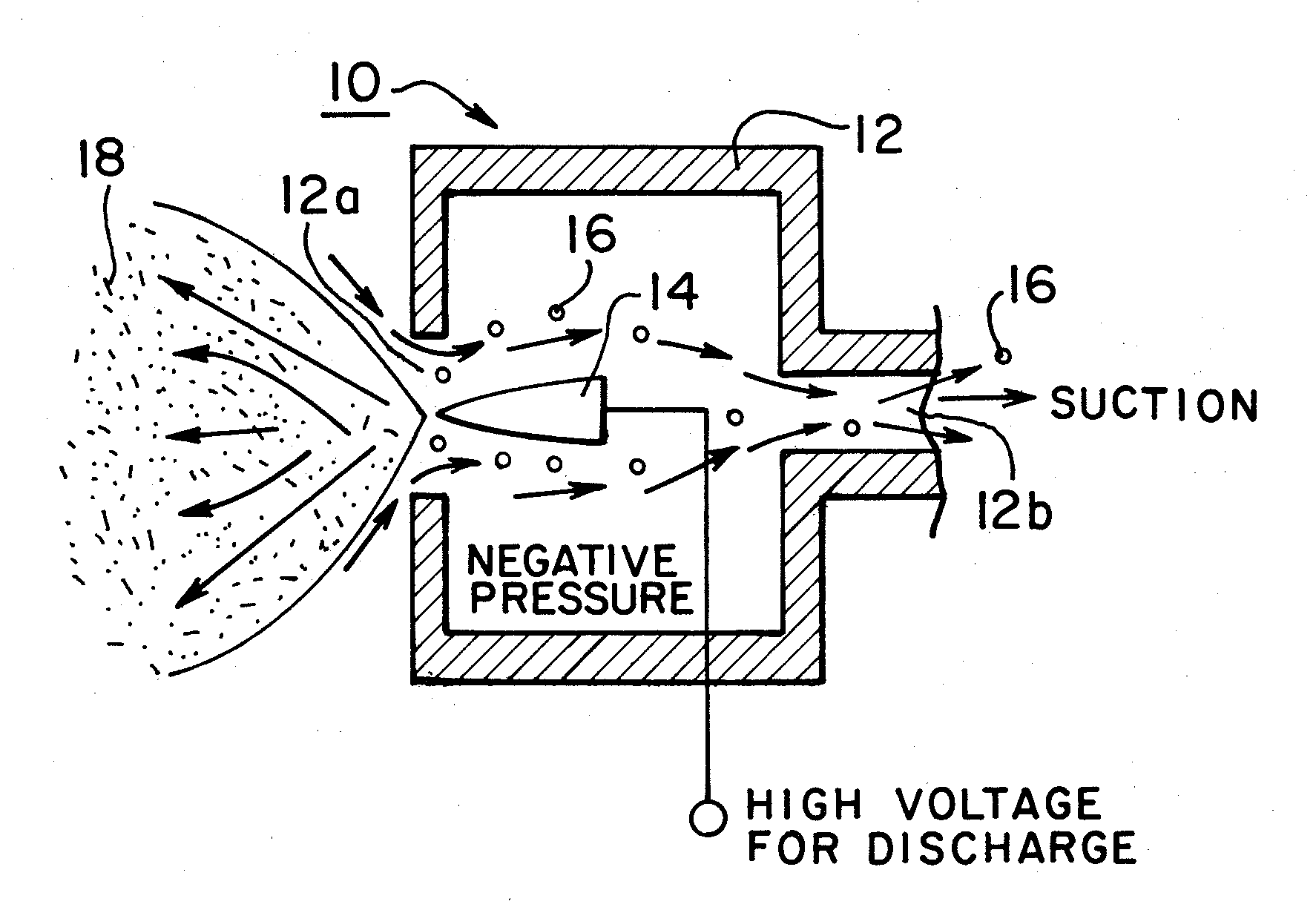
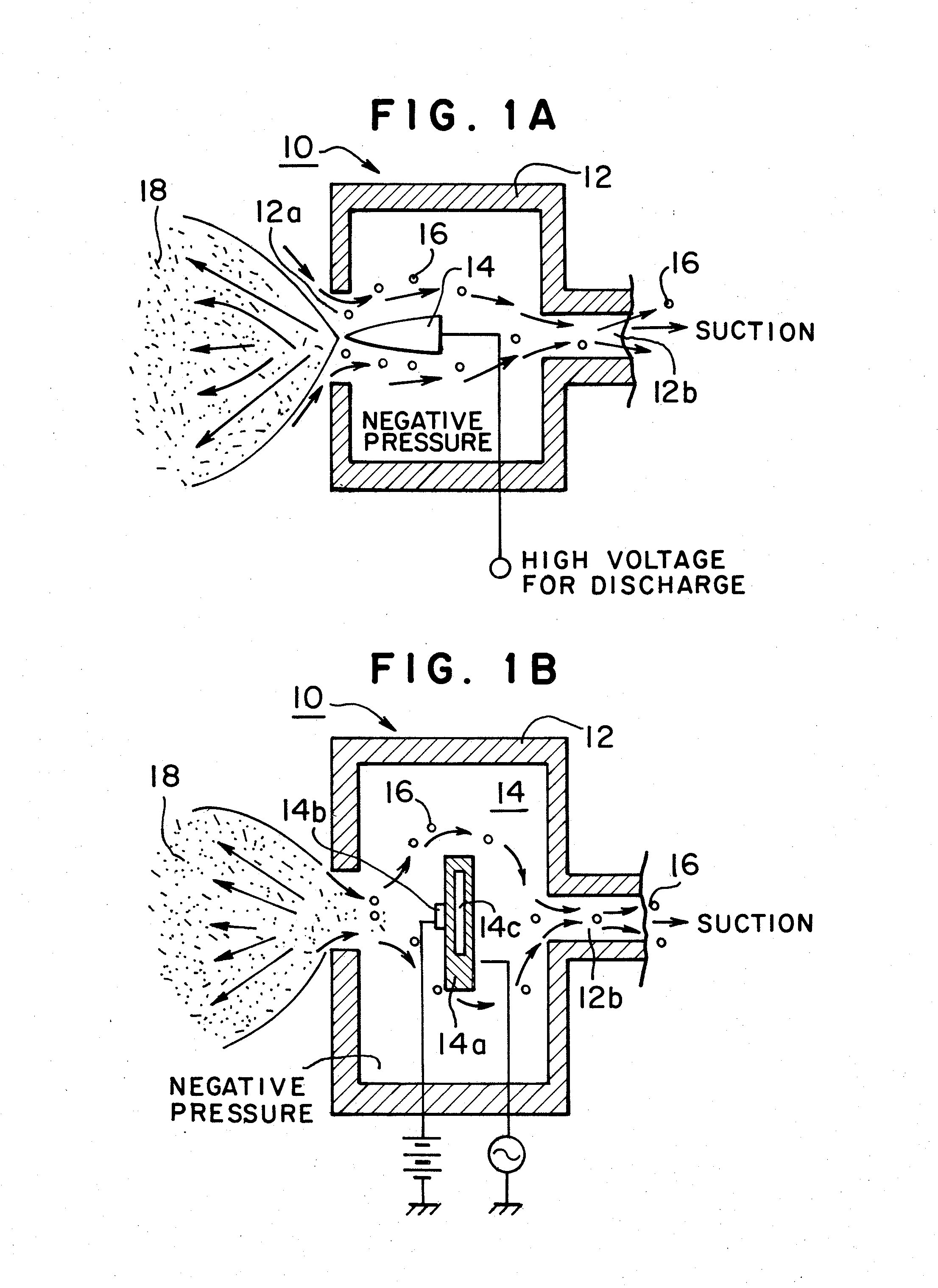
[0017]Now referring to FIG. 1, FIG. 1 is a cross-sectional view showing a first embodiment of static eliminator according to the present invention, FIG. 1A showing a corona discharge case, and FIG. 1B showing a plasma discharge case. In FIG. 1, there is shown an ion generating portion of no-wind type of static eliminator 10 in which ions 18 are flied away without a source of air sender or air blower. A discharge portion 14, discharge needle in the embodiment shown in FIG. 1A, is accommodated in a case 12 which has a ion emitting opening 12a in the front of the discharge portion 14. The ozone and the other flotage generated by electric discharge are collected by sucking air in a direction opposite to ion emitting direction through the ion emitting opening 12a.
[0018]The polarity of ions 18 generated by electric discharge corresponds to the polarity of discharge portion. For example, plus ions are generated from the plus discharge portion. On the other hand, minus ions are generated f...
second embodiment
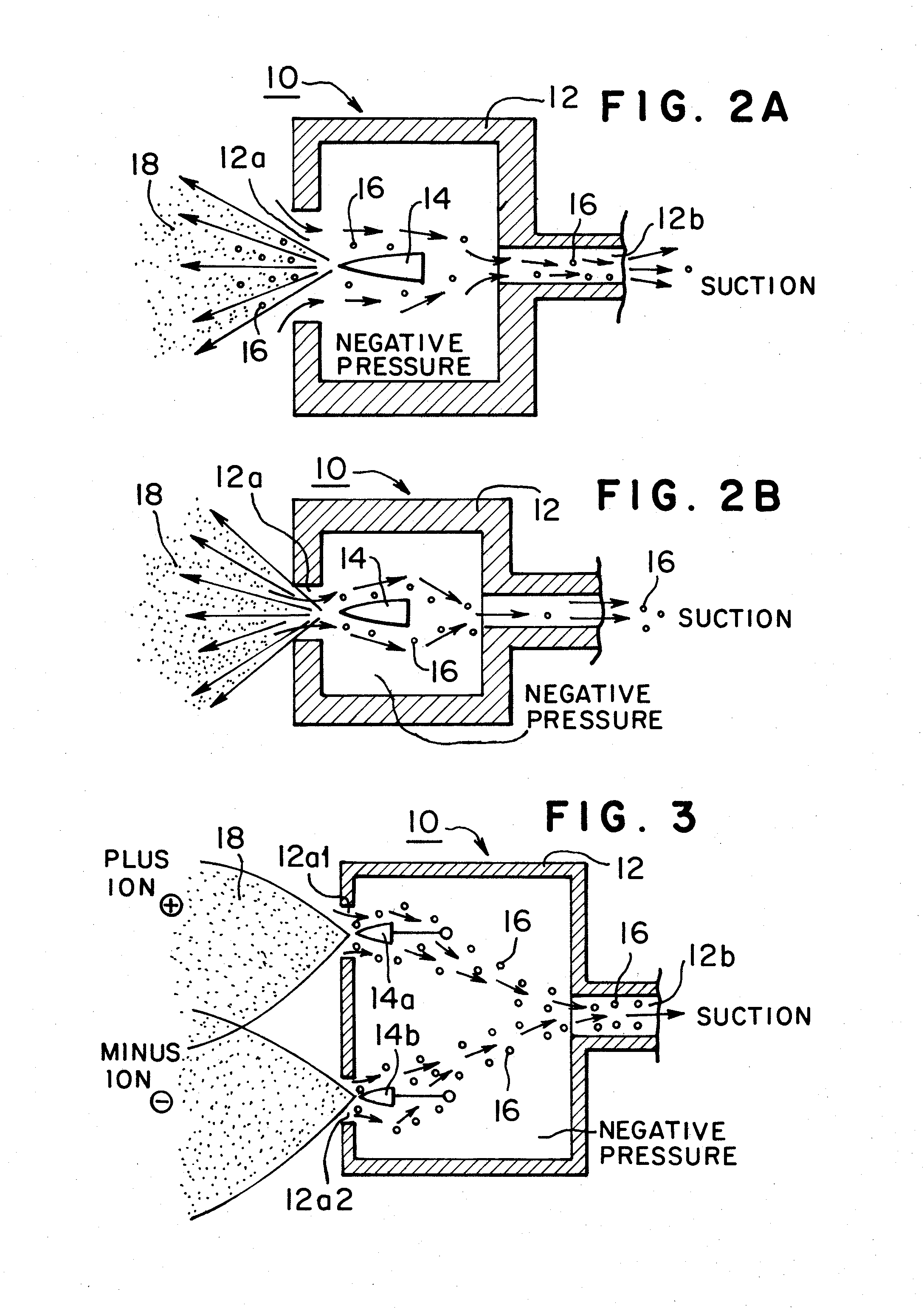
[0022]FIG. 2 is a cross-sectional view showing a second embodiment of static eliminator according to the present invention, FIG. 2A showing a case in that an ion emitting opening is big, and FIG. 2B showing a case in that an ion emitting opening is small. The airflow flowing inward through ion emitting opening 12a should be weak since strong airflow sucks ions and thus ions cannot be emitted through ion emitting opening 12a. Furthermore, it is preferable that the ion emitting opening 12a is as small as possible. In the case of bigger opening shown in FIG. 2a, ion wind blows outward at the center to emit ions 18, and at the same time suction wind blows inward around the center. That is, outward wind and inward wind are generated. The some of ozone and flotage rides the ion wind and goes out. The other of ozone and flotage is collected by the suction wind. As a result, rate of collection becomes worse.
[0023]In the meanwhile, in the case of smaller ion emitting opening shown in FIG. 2B...
third embodiment
[0024]FIG. 3 is a cross-sectional view showing a third embodiment of static eliminator according to the present invention. In FIG. 3, the static eliminator is of d.c. static eliminator or ionizer type without air blow. The static eliminator has discharge portions 14a and 14b for emitting plus and minus ions. The case 12 is provided with suction portion having ozone, etc suction opening 12b to generate negative pressure in the case 12. Plus and minus ions 18 are emitted through ion emitting openings 12a1 and 12a2 while the ozone, etc produced at the discharge portions 14a and 14b rides an airflow which is sucked by the negative pressure and is directed inward from the ion emitting openings 12a1 and 12a2, and then the ozone, etc is collected. In order to collect the ozone, etc more efficiently it is preferable that the airflows which are sucked through the plus and minus ion emitting openings 12a1 and 12a2 are individually controlled.
PUM
 Abstract
Description
Claims
Application Information