LED heat dissipation structure

a heat dissipation structure and led technology, applied in the direction of point-like light sources, semiconductor devices of light sources, light and heating apparatus, etc., can solve the problems of waste heat generation, high energy consumption of conventional lamps, and 89 90% energy loss of input power that generates waste heat, so as to prolong the working life of led devices, improve the efficiency of led devices, and eliminate waste heat accumulation

Inactive Publication Date: 2010-05-27
LING CHYUAN FA ING YONQ
View PDF7 Cites 21 Cited by
  • Summary
  • Abstract
  • Description
  • Claims
  • Application Information

AI Technical Summary

Benefits of technology

[0005]The present invention has been accomplished under the circumstances in view. It is one object of the present invention to provide a LED heat dissipation structure, which eliminates accumulation of waste heat in the LED devices, improving the LED devices' luminous efficiency and prolonging the LED devices' working life.

Problems solved by technology

Conventional lamps have the drawback of high power consumption and do not meet power-saving and environmental protection requirements.
However, LED has the drawback of high percentage, about 89˜90% energy loss of input power that generates waste heat.

Method used


Image

  • LED heat dissipation structure
  • LED heat dissipation structure
  • LED heat dissipation structure

Examples


Embodiment Construction

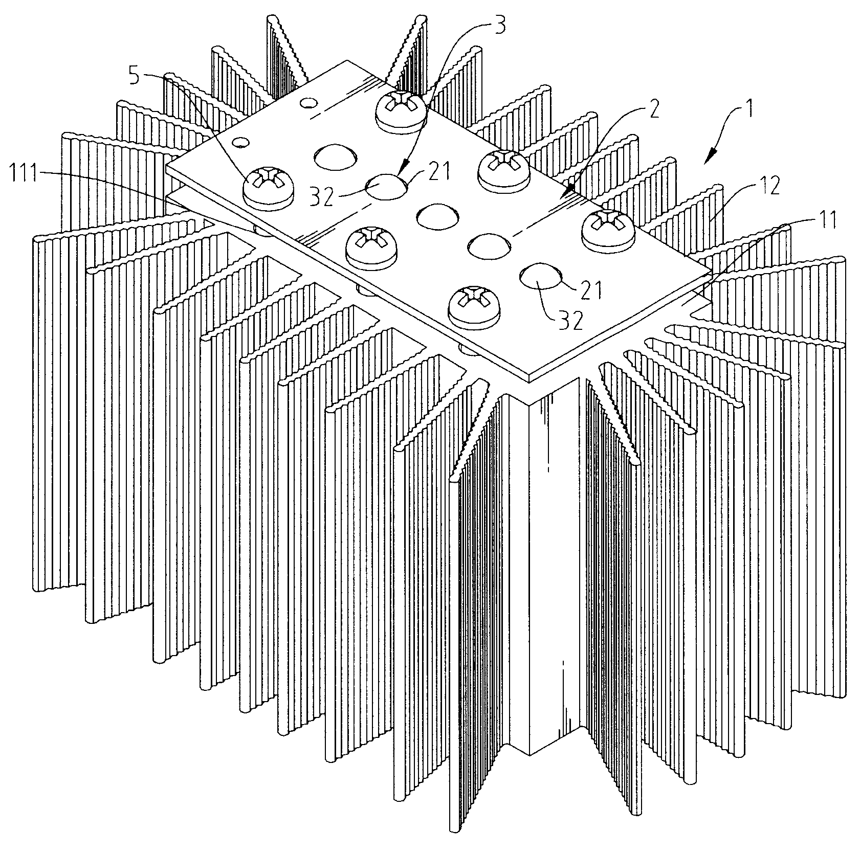
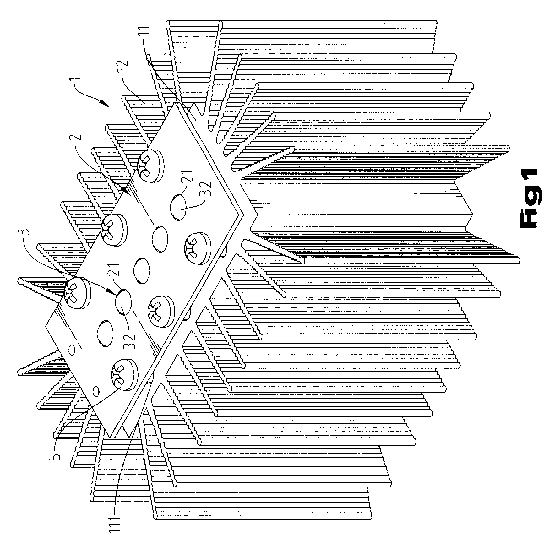
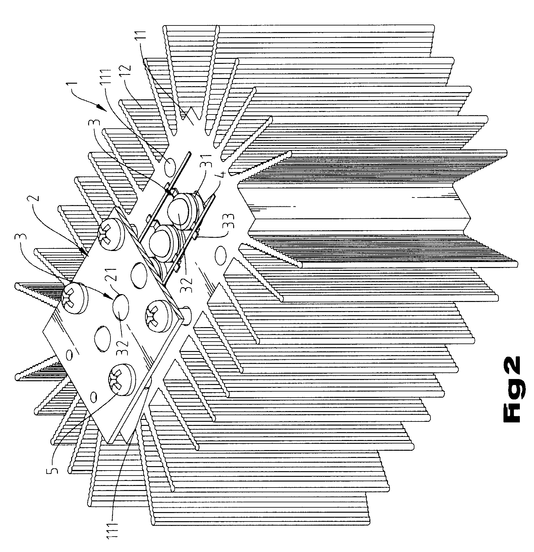
[0012]Referring to FIGS. 1˜3, a LED heat dissipation structure in accordance with the present invention is shown comprising a heat sink 1, a substrate 2 and LED (light emitting diode) devices 3.

[0013]The heat sink 1 is prepared from a high thermal conductivity metal material, having a base block 11, a plurality of radiation fins 12 radially extended from the periphery of the flat base block 11 and a plurality of screw holes 111 located on the flat top wall of the base block 11. The base block 11 may be prepared in any of a variety of shapes. According to this embodiment, the base block 11 has a rectangular configuration.

[0014]The substrate 2 has a circuit layer (not shown) arranged on the bottom wall thereof, a plurality of through holes 21 cut through the top and bottom walls at selected locations and a plurality of mounting holes 22 corresponding to the screw holes 111 of the heat sink 1.

[0015]The LED devices 3 each comprise a body 31, an epoxy lens 32 covering the top side of the...


PUM


Abstract

A LED heat dissipation structure includes a heat sink having a base block and radiation fins, LED devices bonded to the flat top wall of the base block of the heat sink with a thermal compound and a substrate, which is affixed to the base block of the heat sink above the LED devices with screws to hold down the LED devices, having a circuit layer located on the bottom wall thereof and electrically connected with the LED devices to provide the necessary working power supply and a plurality of through holes that accommodate epoxy lenses of the LED devices.

Description

BACKGROUND OF THE INVENTION[0001]1. Field of the Invention[0002]The present invention relates to heat dissipation technology and more particularly, to a LED heat dissipation structure, which dissipates waste heat from light-emitting diode devices rapidly.[0003]2. Description of the Related Art[0004]Conventional lamps have the drawback of high power consumption and do not meet power-saving and environmental protection requirements. Nowadays, LED (light emitting diode) illumination technology has been intensively used to substitute for conventional lighting fixtures, thereby saving power consumption and improving environmental protection. However, LED has the drawback of high percentage, about 89˜90% energy loss of input power that generates waste heat. This waste heat must be quickly dissipated, avoiding lowering LED's luminous efficiency and working life. Therefore, it is important in the LED industry to find a measure to dissipate LED waste heat efficiently.SUMMARY OF THE INVENTION...

Claims


Application Information

Patent Timeline
Patent Type & Authority Applications(United States)
IPC IPC(8): F21V29/00
CPCF21V5/048F21V19/001F21V29/004F21Y2101/02F21Y2103/003F21V29/83F21V29/76F21V29/763F21V29/77F21V29/773F21V29/745F21Y2103/10F21Y2115/10
Inventor PENG, CHING-LUNG
Owner LING CHYUAN FA ING YONQ
Why Eureka
Try Eureka