Light guide plate and backlight module

Active Publication Date: 2010-05-27
AU OPTRONICS CORP
View PDF7 Cites 21 Cited by
  • Summary
  • Abstract
  • Description
  • Claims
  • Application Information

AI Technical Summary

Benefits of technology

[0008]The present invention provides a light guide plate having favorable

Problems solved by technology

The foregoing methods can provide favorable viewing angle

Method used


Image

  • Light guide plate and backlight module
  • Light guide plate and backlight module
  • Light guide plate and backlight module

Examples


Embodiment Construction

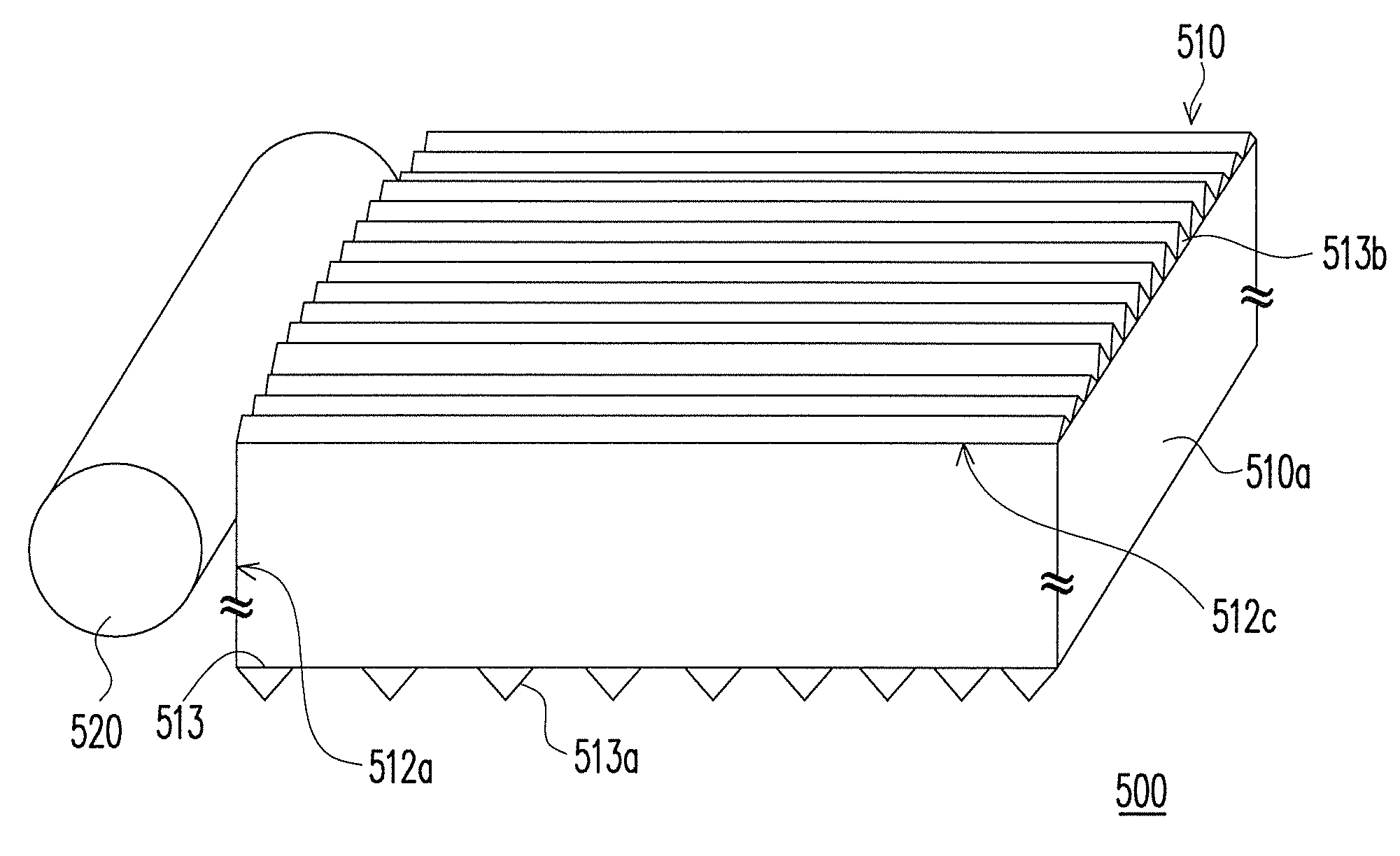
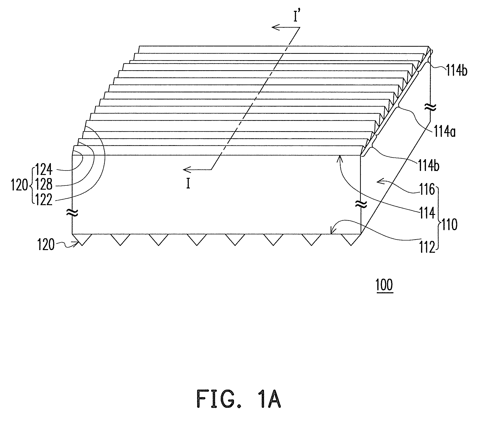
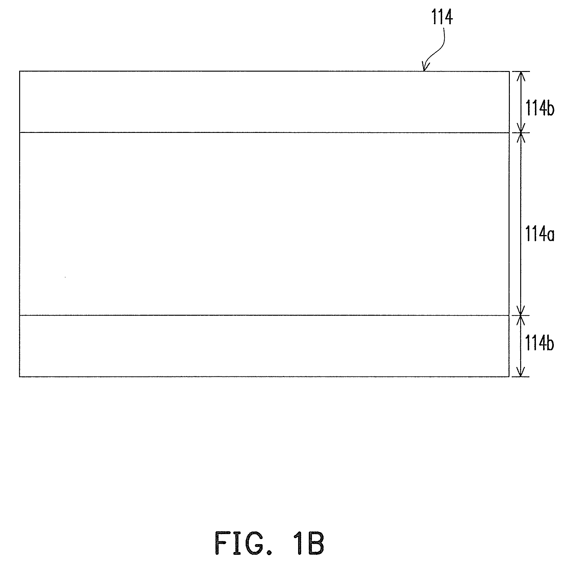
[0027]FIG. 1A is a schematic view of a light guide plate according to one embodiment of the present invention. FIG. 1B is a top view of a light emitting surface of the light guide plate in FIG. 1A. Referring to FIG. 1A, a light guide plate 100 of this embodiment includes a body 110 and a plurality of prism microstructures 120. The body 110 has a bottom surface 112, a light emitting surface 114 opposite to the bottom surface 112, and a plurality of side surfaces 116 connected between the bottom surface 112 and the light emitting surface 114. In this embodiment, as shown in FIG. 1A, the prism microstructures 120 on the bottom surface 112 may be arranged separately or sequentially, which is variable according to actual requirements. With reference to FIG. 1B, the light emitting surface 114 includes a central area 114a and at least one peripheral area 114b disposed outside the central area 114a. In this embodiment, two peripheral areas 114b are illustrated, and the two peripheral areas ...


PUM


Abstract

A light guide plate including a body and a plurality of prism microstructures is provided. The body has a bottom surface, a light emitting surface opposite to the bottom surface, and a plurality of side surfaces. The light emitting surface has a central area and at least one peripheral area outside the central area. The prism microstructures are disposed on the light emitting surface and the bottom surface. The prism microstructure disposed on the light emitting surface includes a plurality of first prism microstructures in the central area and a plurality of second prism microstructures in the peripheral area. A top angle θ2 of the second prism microstructure is greater than a top angle θ1 of the first prism microstructure. A backlight module including the above-mentioned light guide plate is also provided.

Description

CROSS-REFERENCE TO RELATED APPLICATION[0001]This application claims the priority benefit of Taiwan application serial no. 97145560, filed Nov. 25, 2008. The entirety of the above-mentioned patent application is hereby incorporated by reference herein and made a part of specification.BACKGROUND OF THE INVENTION[0002]1. Field of the Invention[0003]The present invention is related to a light guide plate and a backlight module, and particularly to a light guide plate having prism microstructures on two opposite surfaces thereof and a backlight module including the light guide plate.[0004]2. Description of Related Art[0005]A liquid crystal display (LCD) mainly includes two parts, a LCD panel and a backlight module. The LCD panel provides the display function, and the backlight module is used for providing light source. Based on the structure, the backlight module may be categorized into two types, direct-type backlight module and edge-type backlight module. In the edge-type backlight mod...

Claims


Application Information

Patent Timeline
IPC IPC(8): F21V7/22
CPCG02B6/0046G02B6/0038
Inventor WANG, CHIUNG-HANLIAO, JING-HUANHUANG, YU-TSUNG
Owner AU OPTRONICS CORP
Why Eureka
Try Eureka