Optical transmission systems, devices, and methods

a transmission system and optical transmission technology, applied in the field of optical transmission systems, devices, and methods, can solve the problems of significantly lower network cost than dedicated protection or mesh restoration, and achieve the effects of low cost, improved operational flexibility, and efficient optical communication systems

Inactive Publication Date: 2010-05-27
LEVEL 3 COMM LLC
View PDF12 Cites 37 Cited by
  • Summary
  • Abstract
  • Description
  • Claims
  • Application Information

AI Technical Summary

Benefits of technology

[0032]The present invention is directed generally to improved optical communications systems, devices, and methods which may include grooming, protection, restoration, and migration on a unified network platform, and which may use a unified control plane. The systems may include combinations of optical bypass and mesh restoration, may include combinations of shared mesh, dedicate protection, or other protection, and may be combinations of long haul, extended long haul, and ultra long haul systems. The systems may also include a configurable DWDM tier to accommodate dynamic traffic patterns, thereby allowing for increased operational flexibility. The present invention enables efficient, low cost optical communications systems, devices, and methods.
[0033]One embodiment of the present invention is directed to systems including new network elements or nodes that combine the cost efficiency of optical by-pass and the flexibility and fine granularity of a grooming cross-connect, referred to as the “unified network platform”. A strong interaction between the grooming cross-connect layer and the dynamic DWDM layer provides increased flexibility in order to accommodate traffic changes or uncertainties in traffic demands.
[0034]Another embodiment of the present invention is directed to grooming architectures which support a smooth transition from low traffic levels, where traffic may be groomed at several nodes along its route, to high traffic levels where intermediate grooming is not required and optical bypass dramatically decreases the cost of the network.

Problems solved by technology

Moreover, dedicated protection can be used to provide additional optical bypass and cost reduction, which combined with mesh restoration results in network cost significantly lower than mesh restoration or dedicated protection alone.

Method used


Image

  • Optical transmission systems, devices, and methods
  • Optical transmission systems, devices, and methods
  • Optical transmission systems, devices, and methods

Examples


Embodiment Construction

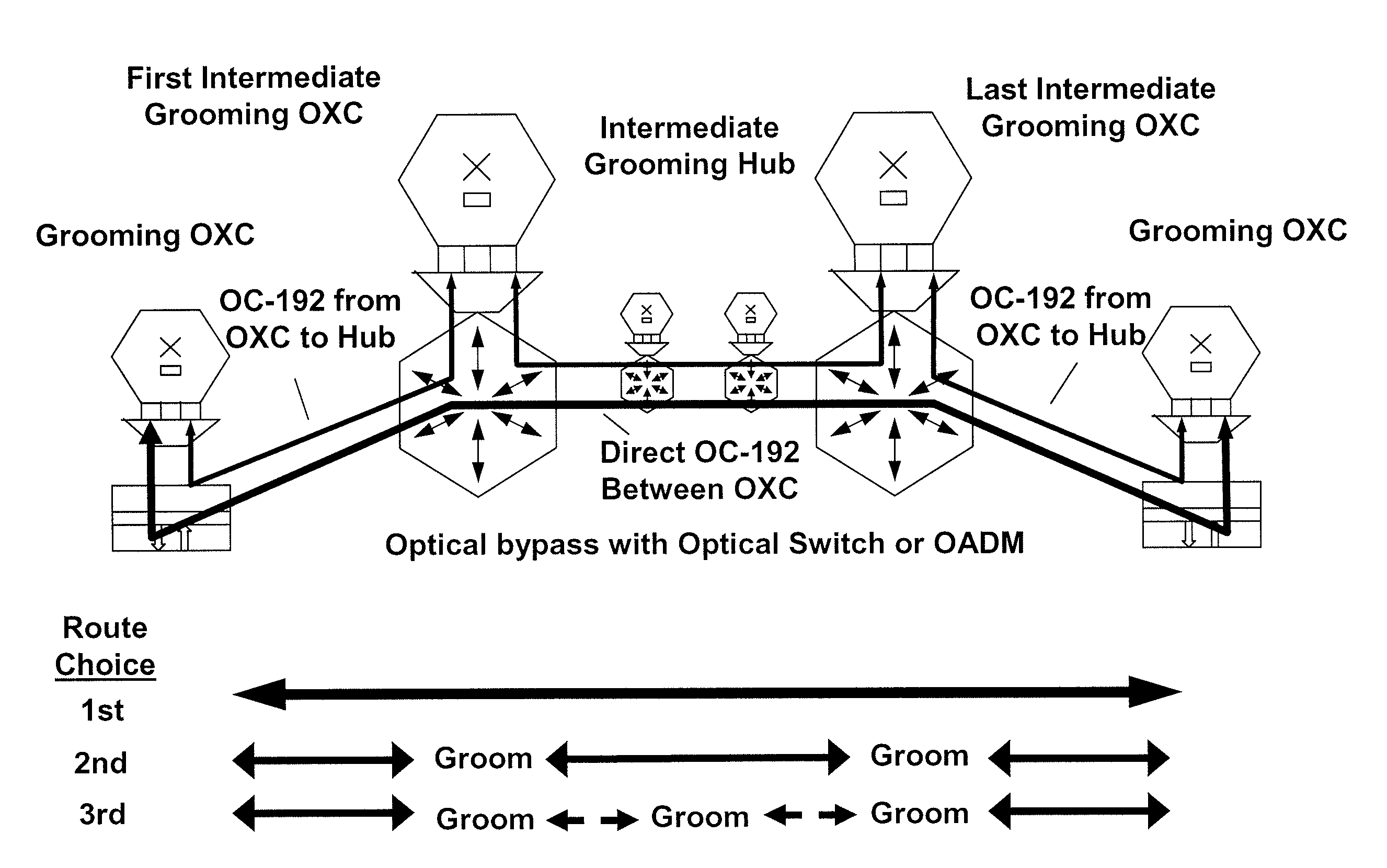
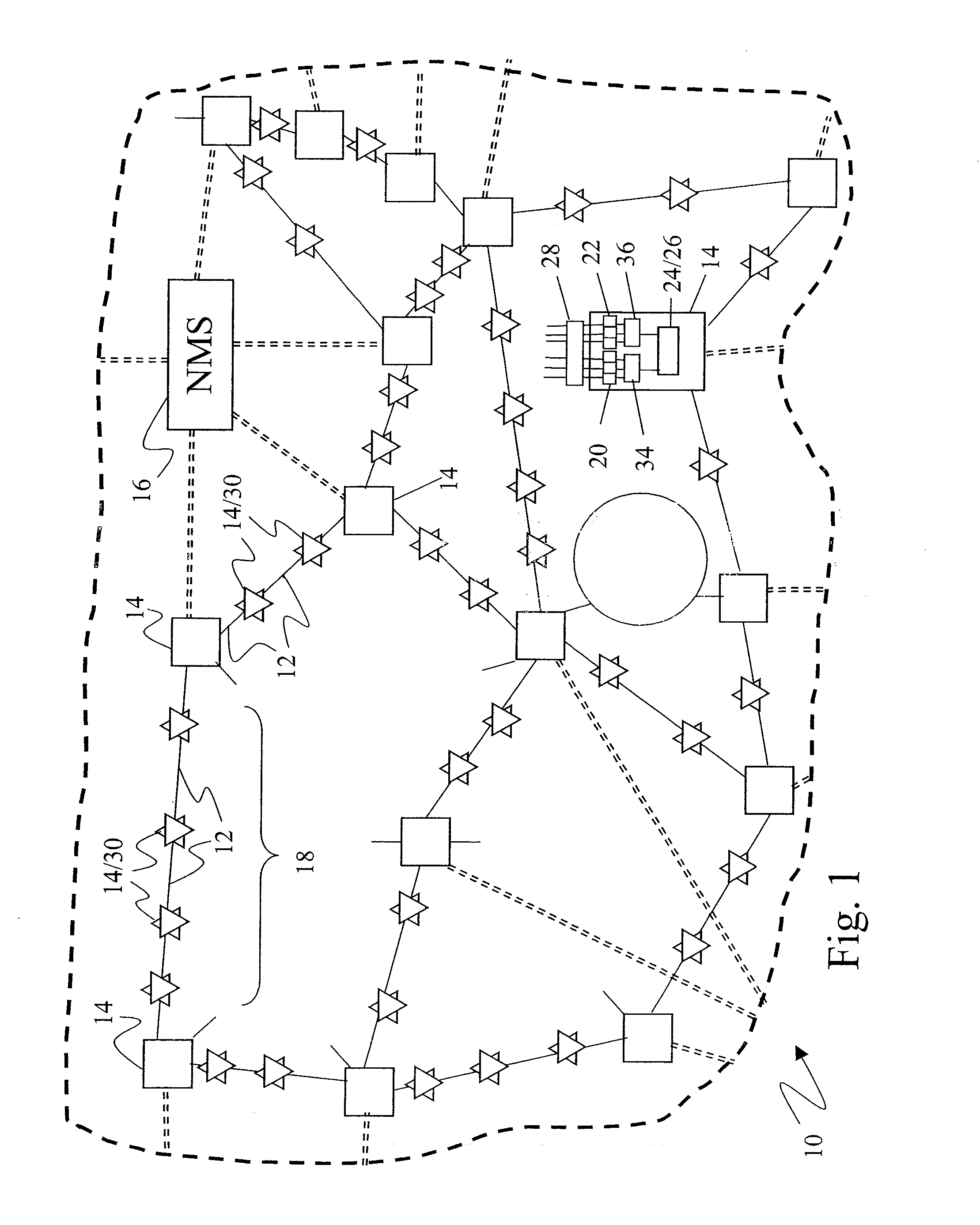
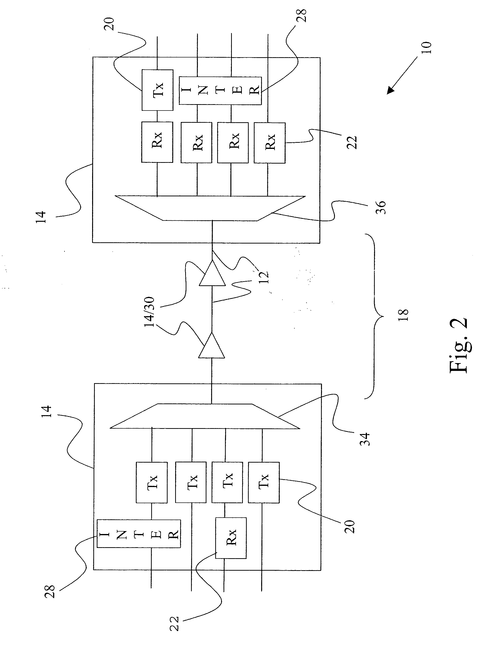
[0040]FIG. 1 illustrates an optical communications system 10 which includes optical paths 12 connecting nodes and network elements 14. Advantages of the present invention can be realized with many system 10 configurations and architectures, such as an all optical network, one or more point to point links, one or more rings, a mesh, other architectures, or combinations of architectures. The system 10 illustrated in FIG. 1 is a multi-dimensional network, which can be implemented, for example, as an all optical mesh network, as a collection of point to point links, or as a combination of architectures. The system 10 can employ various signal formats, and can also convert between formats. The system 10 can also include more or less features than those illustrated herein, such as by including or deleting a network management system (“NMS”) 16 and changing the number, location, content, configuration, and connection of nodes 14.

[0041]The optical paths 12 can include guided and unguided tr...


PUM


Abstract

Optical communications systems including grooming, protection, restoration, and migration on a unified network platform, and using a unified control plane. The systems may include combinations of optical bypass and mesh restoration, may include combinations of shared mesh and dedicate protection, and may be combinations of long haul, extended long haul, and ultra long haul systems. The systems may also include a configurable DWDM tier to accommodate dynamic traffic patterns, thereby allowing for increased operational flexibility.

Description

CROSS-REFERENCE TO RELATED APPLICATIONS[0001]This application claims priority from U.S. Provisional Patent Application No. 60 / 385,758, filed Jun. 4, 2002, and which is incorporated herein by reference.STATEMENT REGARDING FEDERALLY SPONSORED RESEARCH OR DEVELOPMENT[0002]Not Applicable.BACKGROUND OF THE INVENTION[0003]The development of digital technology provided the ability to store and process vast amounts of information. While this development greatly increased information processing capabilities, it was soon recognized that in order to make effective use of information resources it was necessary to interconnect and allow communication between information resources. Efficient access to information resources requires the continued development of information transmission systems to facilitate the sharing of information between resources. One effort to achieve higher transmission capacities has focused on the development of optical transmission systems. Optical transmission systems c...

Claims


Application Information

Patent Timeline
Patent Type & Authority Applications(United States)
IPC IPC(8): H04J14/02
CPCH04J14/0212H04J14/0275H04J14/0217H04J14/0283H04J14/0284H04J14/0289H04J14/0293H04Q11/0062H04Q11/0071H04Q2011/0081H04Q2011/0098H04J14/0241H04J14/0256H04J14/0258H04J14/0267H04J14/0268H04J14/0213
Inventor WESTON-DAWKES, JONATHAN L.BARONI, STEFANOTRNKUS, MARIANBENMOHAMED, LOTFI M.RONARC'H, JEAN-LUC
Owner LEVEL 3 COMM LLC
Why Eureka
Try Eureka