Centrifugal Compressor

a centrifugal compressor and compressor technology, applied in the direction of machines/engines, stators, liquid fuel engines, etc., can solve the problem of difficult to measure the internal flow of airflow flowing within the diffuser passage, and achieve the effect of reducing the surge flow rate and widening the compressor operation rang

Inactive Publication Date: 2010-05-27
MITSUBISHI HEAVY IND LTD
View PDF3 Cites 18 Cited by
  • Summary
  • Abstract
  • Description
  • Claims
  • Application Information

AI Technical Summary

Benefits of technology

[0022]According to the present invention described above, since on the hub side wall surface of the diffuser passage there is provided the inclined area that approaches the shroud side in the position on the downstream side of the portion parallel with the normal line of the impeller exit section, the radial direction velocity of a low velocity area that occurs on the hub side wall surface increases in this inclined area. Therefore, the radial direction velocity distribution within the diffuser passage is made uniform, and separation of the airflow is unlikely to occur locally, so that the surge flow rate can be reduced and the compressor operation range can be widened.

Problems solved by technology

However, in a small centrifugal compressor such as a turbo charger for a motor vehicle in particular, it is difficult to measure the internal flow of the airflow flowing within the diffuser passage.

Method used


Image

  • Centrifugal Compressor
  • Centrifugal Compressor
  • Centrifugal Compressor

Examples


Embodiment Construction

[0043]Hereunder an embodiment of a centrifugal compressor according to the present invention is described, based on the drawings.

[0044]As shown in FIG. 5A, a centrifugal compressor 10 is provided with a diffuser passage 15 that recovers static pressure by reducing the velocity of a discharged air from an outer circumferential end of an impeller 13 that rotates within a housing 11. The diffuser passage 15 is provided so as to connect between an impeller exit (diffuser entry) 14 and a scroll 16, and is formed in between a pair of opposing wall surfaces that comprise a shroud side wall surface 15a and a hub side wall surface 15b.

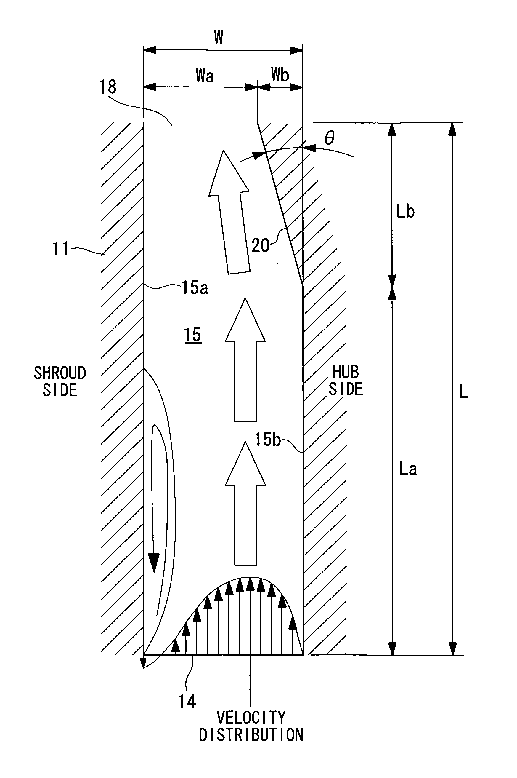
[0045]FIG. 1 is a sectional view of the diffuser passage 15 showing a first embodiment. This diffuser passage 15 introduces from the diffuser entry 14, the discharged air (indicated with white arrows in the drawing) from the outer circumferential end of the impeller 13, and allows the airflow guided to the passage between the shroud side wall surface 15a and t...


PUM


Abstract

There is provided a centrifugal compressor having a diffuser structure in which airflow is unlikely to separate from a hub side wall surface on a hub side wall surface downstream side within a diffuser passage. In a centrifugal compressor provided with a diffuser passage 15 for recovering static pressure by slowing down discharged air from an outer circumferential end of an impeller that rotates within a housing 11, a hub side wall surface 15b of the diffuser passage 15 is provided with an inclined plane 20 that approaches toward a shroud side, in a position on a downstream side of a portion parallel with a normal line direction of a section surface of an impeller exit.

Description

TECHNICAL FIELD[0001]The present invention relates to a centrifugal compressor of a turbo charger or the like.BACKGROUND ART[0002]Conventionally, a centrifugal compressor of a turbo charger or the like to be used for an internal combustion engine of a motor vehicle for example, is commonly known.[0003]FIG. 5A is a sectional view showing a relevant section of a conventional centrifugal compressor. A centrifugal compressor 10 shown in the drawing compresses fluid such as gas and air introduced from outside a housing 11, by rotating an impeller 13 having a large number of blades 12 within the housing 11. The fluid flow (airflow) formed in this way travels through an impeller exit (Hereunder, also referred to as “diffuser entry”) 14, being an outer circumferential end of the impeller 13, then through a diffuser passage 15 and a scroll 16, and is then delivered to the outside. Reference symbol 17 in the drawing denotes a shaft axis about which the impeller 13 rotates.[0004]The diffuser p...

Claims


Application Information

Patent Timeline
Patent Type & Authority Applications(United States)
IPC IPC(8): F04D29/44
CPCF04D29/441F05D2250/52F04D29/002F04D29/403F05D2210/12F05D2260/60Y10S415/00Y10S417/00
Inventor SUGIMOTO, KOICHISHIRAISHI, TAKASHIHIGASHIMORI, HIROTAKAISOBE, HIDEYOSHI
Owner MITSUBISHI HEAVY IND LTD
Why Eureka
Try Eureka