Ultra-Resilient Fabric

a fabric, ultra-resilient technology, applied in the direction of resilient fabrics, weaving, press sections, etc., can solve the problems of reducing the affecting the quality of the fabric, and the density of the fabric is not ideal, so as to achieve the effect of high degree of compressibility and resiliency

Active Publication Date: 2010-05-27
ALBANY INT CORP
View PDF60 Cites 34 Cited by
  • Summary
  • Abstract
  • Description
  • Claims
  • Application Information

AI Technical Summary

Benefits of technology

[0033]The resilient compressible fabric can form or be included in any number of final fabrics including: paper machine clothing, such as a forming fabric, a press fabric, a dryer fabric, a through air dryer fabric, a shoe press belt base, a calendar belt base, or a transfer belt base; an engineered fabric base; or a fabric used in the production of nonwovens by processes such as airlaid, melt blowing, spunbonding, and hydroentangling; or an industrial process belt such as a textile finishing belt, or other belts that require a high degree of compressibility and resiliency. Where the fabric is a base for a dryer fabric, the dryer fabric can include a backside or a non-sheet contact side of the fabric, the backside including angled components.
[0034]In another embodiment, the fabric is a compressible resilient industrial fabric, wherein the fabric comprises: one or more layers of a plurality of functional yarns in the machine direction (MD) and / or cross-machine direction (CD), and one or more layers of a plurality of hollow elastic (axially and radially) members interspersed between the one or more layers of a plurality of functional yarns. Any number of the MD yarns and CD yarns are interwoven to form a woven fabric. The fabric further can include a plurality of binder yarns. Also, the fabric can comprise a 2-8-shed pattern. The compressible resilient fabric can be woven into any of a flat woven fabric, an endless fabric; and an on-machine seamable fabric. In one embodiment the fabric can include a laminated structure. For example, the fabric can comprise two woven layers with the inventive compressible resilient fabric there between. As another example, the fabric can comprise binder yarns weaving between the layers of laminate. In another embodiment, the binder yarns and the hollow elastic members of the fabric can be in the same direction, for example, the CD. Binder yarns may be in the MD instead, or in both MD and CD. In such an embodiment, the layer of hollow elastic members can be inside a double layer construction. The hollow elastic members are preferably coarser (larger) than the binder yarns. Also, the fabric can comprise the hollow elastic members in the CD and the MD, wherein the binder yarns are smaller than the hollow elastic members.
[0035]The interwoven resilient compressible fabric can form or be included in any number of final fabrics including: paper machine clothing, such as a forming fabric, a press fabric, a dryer fabric, a through air dryer fabric, a shoe press belt base, a calendar belt base, or a transfer belt base; an engineered fabric base; or a fabric used in the production of nonwovens by processes such as airlaid, melt blowing, spunbonding, and hydroentangling; or an industrial process belt such as a textile finishing belt, or other belts that require a high degree of compressibility and resiliency. Where the fabric is a base for a dryer fabric, the dryer fabric can include a backside or a non-sheet contact side of the fabric, the backside including angled components.

Problems solved by technology

While there have been various attempts to change the degree of compressibility, press fabrics become progressively thinner over time and millions of nip cycles.
Eventually they must be removed due to various reasons such as lack of water handling capability, marking, or press vibration.
New fabrics also go through a break in period wherein the density is not ideal and water handling is less than optimum.
The compressibility is only due to the elastic portion (in the through thickness direction) of the yarn, and is therefore limited to such.
While larger yarns can be used, there is eventually a diminishing return on performance.
Also large yarns are heavy, and can cause objectionable sheet marking.
If the yarn is a sheath / core type, there is always the danger of delamination of the sheath from the core.
Such yarn sizes can be limited in use due to weight and potential marking considerations.
But again, using these yarns, the compressibility and spring back is limited to some portion of the yarn diameter at most.
As stated above, because of this limited resiliency, press fabrics have a relatively high void volume to handle water when new, more than is ideally required.
However as they have limited resiliency, they will continue to compact, eventually requiring removal and replacement.

Method used


Image

  • Ultra-Resilient Fabric
  • Ultra-Resilient Fabric
  • Ultra-Resilient Fabric

Examples


Embodiment Construction

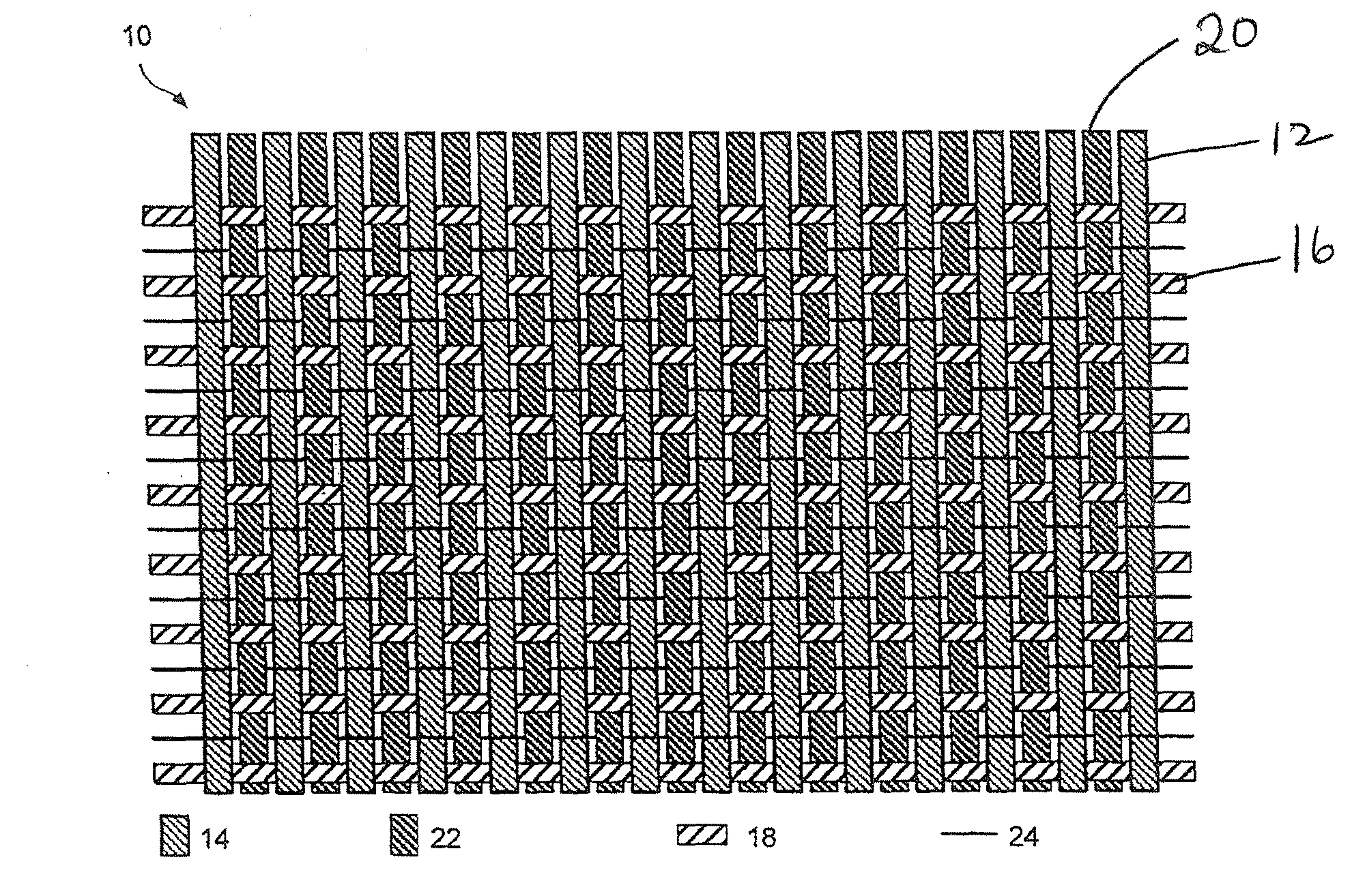
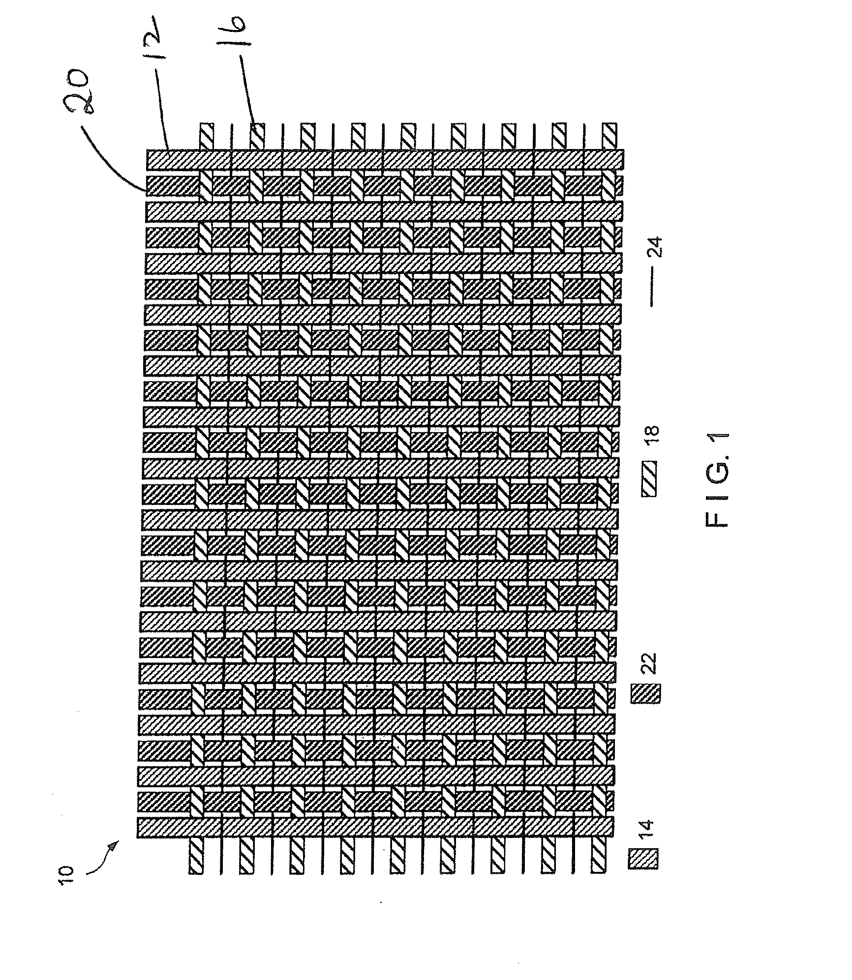
[0050]Initially although a press fabric will be discussed, as aforesaid the present invention has application to other type fabrics or belts including forming fabrics, dryer fabrics, through air dryer fabrics, shoe press belts, calendar belts, or transfer belts; engineered fabrics; or fabrics used in the production of nonwovens by processes such as airlaid, melt blowing, spunbonding, and hydroentangling; or industrial process belts such as textile finishing belts, or other belts that require a high degree of compressibility and resiliency.

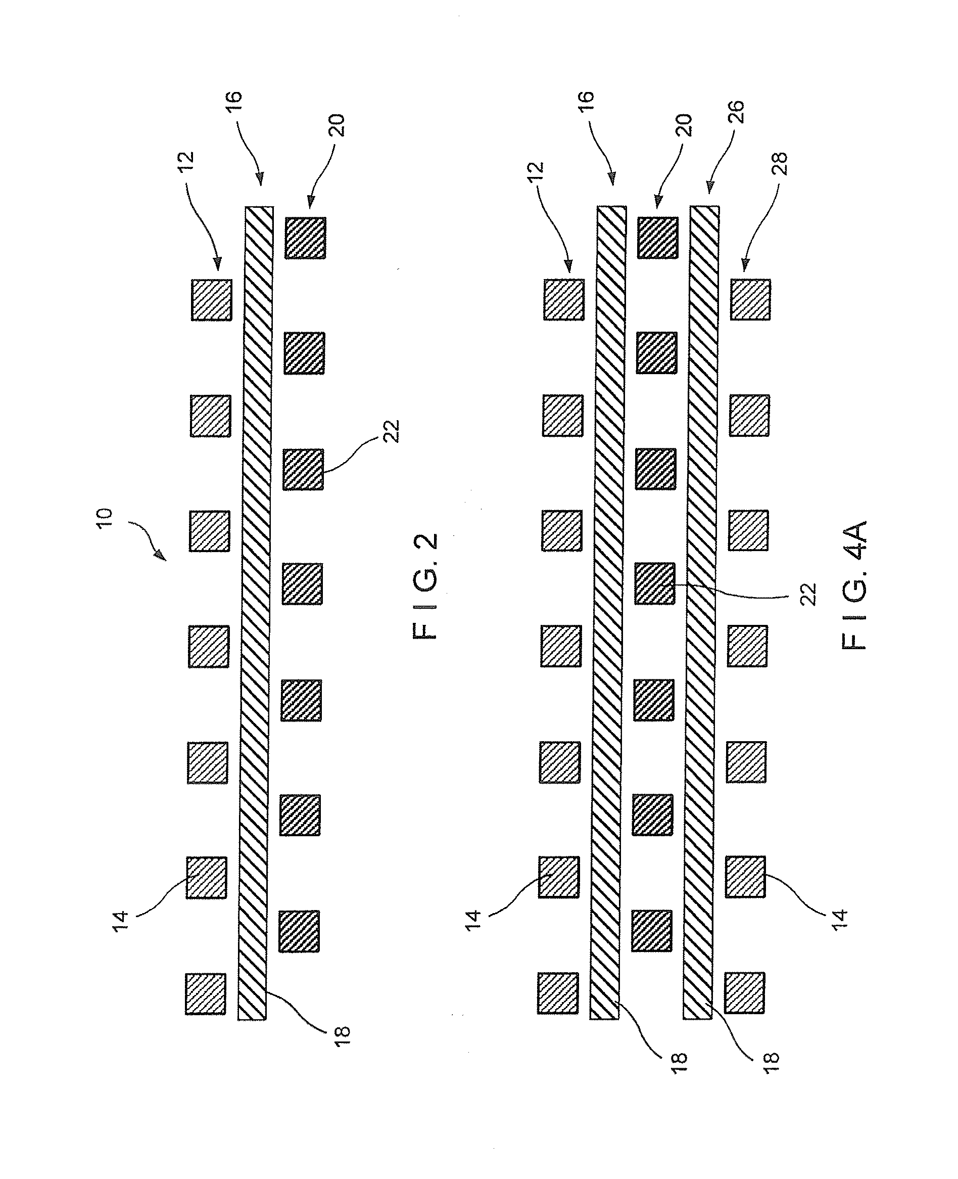
[0051]A hollow member that is defined as elastic in its thickness or radial direction and length or axial direction is required for all the embodiments discussed herein. The hollow elastic member can have any form as appropriate for the application and can be, for example, single monofilament, plied monofilament or multifilament, wrapped member of different materials, multicomponent member, knitted member, twisted member, or braided. The hollow ela...


PUM

PropertyMeasurementUnit
angleaaaaaaaaaa
angleaaaaaaaaaa
sizeaaaaaaaaaa

Abstract

A structure for use in industrial fabrics such as paper machine clothing and engineered fabrics is disclosed. The structure includes axially and radially elastic hollow members, and relatively inelastic yarns in various patterns. The structure has a high degree of both compressibility under an applied normal load and excellent recovery (resiliency or spring back) upon removal of that load.

Description

CROSS-REFERENCE TO RELATED APPLICATION[0001]This application is a continuation-in-part of U.S. application Ser. No. 12 / 345,466 filed Dec. 29, 2008, which claims priority of U.S. Provisional Patent Application Ser. No. 61 / 017,484 filed Dec. 28, 2007, the entire disclosures of which are incorporated herein by reference.FIELD OF THE INVENTION[0002]The present invention relates to structures for use in industrial fabrics such as paper machine clothing and engineered fabrics. More specifically, the structures include hollow elastic members, which may be compressible in a thickness or radial direction and resilient in a length or axial direction, and relatively inelastic functional yarns in various patterns. Such structures have a high degree of both compressibility under an applied normal load and excellent recovery (resiliency or spring back) upon removal of that load.BACKGROUND OF THE INVENTION[0003]Industrial fabrics means an endless structure in the form of a continuous loop such as ...

Claims


Application Information

Patent Timeline
Patent Type & Authority Applications(United States)
IPC IPC(8): B32B5/12B32B5/26B32B7/03D03D15/56
CPCB32B5/26Y10T428/24074D03D1/0094D03D7/00D03D11/00D03D15/0044D03D15/0083D03D15/08D10B2401/046D21F1/0036D21F3/0227D21F7/083D21F7/086D03D13/004B65G15/34B32B5/026B32B5/12B32B2250/03B32B2262/02B32B2262/0292B32B2307/51B32B2307/514B32B7/03Y10T442/30D03D15/497D03D15/44D03D15/56
Inventor HANSEN, ROBERT A.RYDIN, BJORNLUCIANO, WILLIAM
Owner ALBANY INT CORP
Why Eureka
Try Eureka