Post-weld offset gage

Inactive Publication Date: 2010-06-03
GENERAL ELECTRIC CO
View PDF7 Cites 3 Cited by
  • Summary
  • Abstract
  • Description
  • Claims
  • Application Information

AI Technical Summary

Benefits of technology

[0011]One advantage of the present disclosure includes being able to determine whether a weld is undesirable.
[0014]Another advantage of the present disclosure is increased consistency in measurements due to the added stability attributable to only one member touching each surface.
[0016]Another advantage of the present disclosure is the ability to analyze a formed weld with an inexpensive and relatively simple process.

Problems solved by technology

The welded parts may be subjected to numerous physical forces.
If a weld of the welded components is unsuccessful, the parts may be more susceptible to failure.
For example, force supplied by wind and / or force supplied by rotation of the blades on a wind turbine can produce fatigue loading on towers in the wind turbine.
This fatigue can result in failure of the weld and failure of the wind tower.
Generally, when parts are welded, the method for analyzing whether a weld has the desired mechanical properties is performed during the process of welding or involves complex and / or expensive analytical instruments.

Method used


Image

  • Post-weld offset gage
  • Post-weld offset gage
  • Post-weld offset gage

Examples


Embodiment Construction

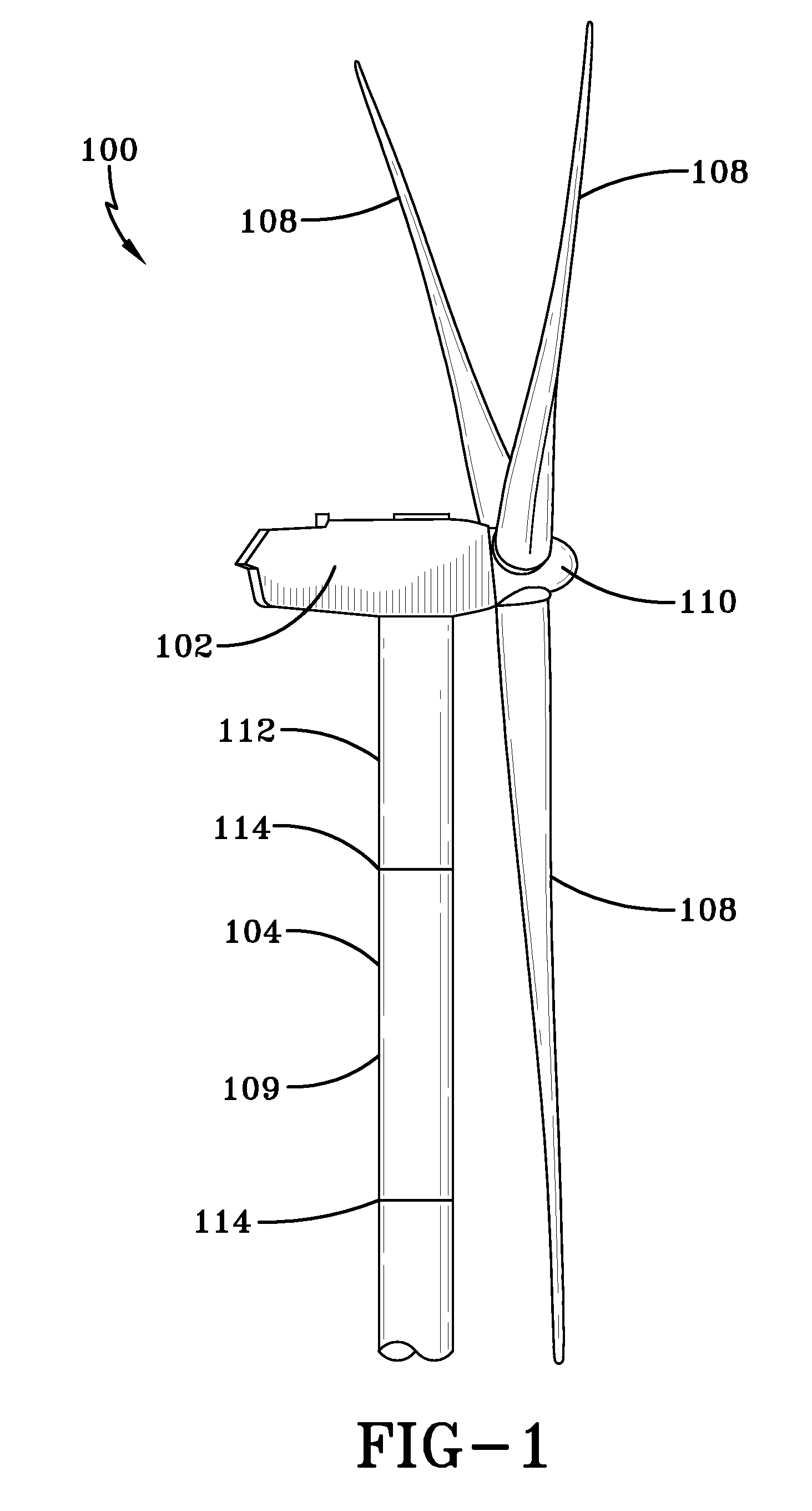
[0027]As shown in FIG. 1, a wind turbine system 100 generally comprises a nacelle 102 housing a generator (not shown). Nacelle 102 can be a housing mounted atop a tower 104. Wind turbine system 100 can be installed on various types of terrain providing access to areas having desirable wind conditions. The terrain may vary greatly and may include, but is not limited to, mountainous terrain or off-shore locations. Wind turbine system 100 can also include one or more rotor blades 108 attached to a rotating hub 110. System 100 can include the generator for converting rotation of rotor blades 108 into electrical power.

[0028]Tower 104 can include a first portion 109 secured to a second portion 112 by a weld 114. The weld described herein is a formed weld. As used herein, the term “formed weld” includes welds formed through heating, ultrasonic welding, and any other suitable welding process. For example, the formed weld produced by heating may be a cooled weld. As shown, first portion 109 ...


PUM


Abstract

A method and device for analyzing a formed weld of a wind turbine system is disclosed. The device includes a gage for measuring a distance, a first member configured for receiving the gage, a second member attached to the first member, the second member being configured to releasably attach to a first surface on a first side of the formed weld, a third member attached to the first member, the third member being configured to releasably attach to a second surface on a second side of the formed weld, and the gage being positionable at a plurality of locations on the first member, the plurality of locations including a first location being proximal to the second member and distal from the third member and a second location being proximal to the third member and distal from the second member.

Description

FIELD[0001]The present disclosure generally relates to a device and method for analyzing welds. In particular, the present disclosure relates to a device and method for analyzing off-set or otherwise undesirable welds on wind turbine towers after the welds have been formed.BACKGROUND[0002]Recently, wind turbines have received increased attention as an environmentally safe and a relatively inexpensive alternative energy source. With this growing interest, considerable efforts have been made to develop wind turbines that are reliable and efficient.[0003]Generally, a wind turbine can include a plurality of blades coupled to a generator rotor through a hub. The generator rotor can be mounted within a housing or nacelle, which may be positioned on top of a tubular tower or a base. The hub and blades may form a wind turbine rotor. Utility grade wind turbines (for example, wind turbines designed to provide electrical power to a utility grid) can have large wind turbine rotors (for example,...

Claims


Application Information

Patent Timeline
IPC IPC(8): G01L1/22
CPCY02E10/72G01B21/20
Inventor SIEBER, KURT
Owner GENERAL ELECTRIC CO
Why Eureka
Try Eureka