Film deposition apparatus

a technology of film deposition apparatus and film, which is applied in the direction of chemical vapor deposition coating, coating, coating process, etc., can solve the problems of complex maintenance work, residuals may fall, and the elevation mechanism for lifting the top panel ends up requiring a large amount of power, so as to achieve convenient maintenance work

Active Publication Date: 2010-06-03
TOKYO ELECTRON LTD
View PDF21 Cites 44 Cited by
  • Summary
  • Abstract
  • Description
  • Claims
  • Application Information

AI Technical Summary

Benefits of technology

[0020]According to a first aspect, a film deposition apparatus allowing easy maintenance work is provided in which a rotary table to support wafers placed thereon is rotated in a vacuum container to revolve the wafers, which are subjected to a film deposition process performed by reactant gases supplied through reactant gas nozzles.

Problems solved by technology

This requires the reactant gas pipes to be disconnected from the top panel, which complicates the maintenance work.
When reactant gases have left residuals inside the pipes, these residuals may fall due to the manual handling of the pipes, which may end up being undesirable particles.
Since such a preparatory treatment unit is generally bulky and heavy, an elevation mechanism for lifting the top panel ends up requiring a large amount of power.
This limits the choice of location where the apparatus is installed.

Method used


Image

  • Film deposition apparatus
  • Film deposition apparatus
  • Film deposition apparatus

Examples


Embodiment Construction

[0068]In the following, embodiments of the present invention will be described with reference to the accompanying drawings.

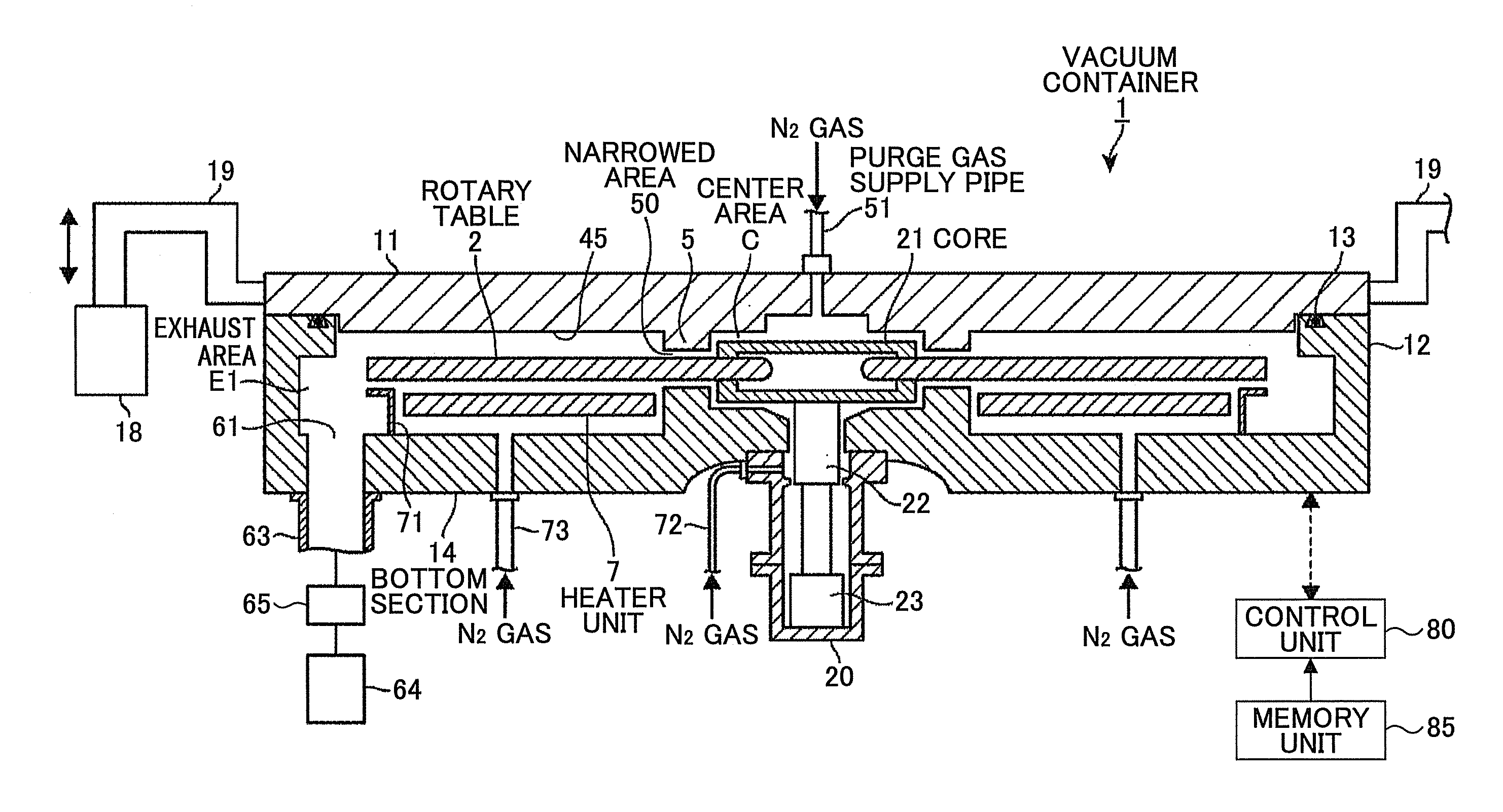
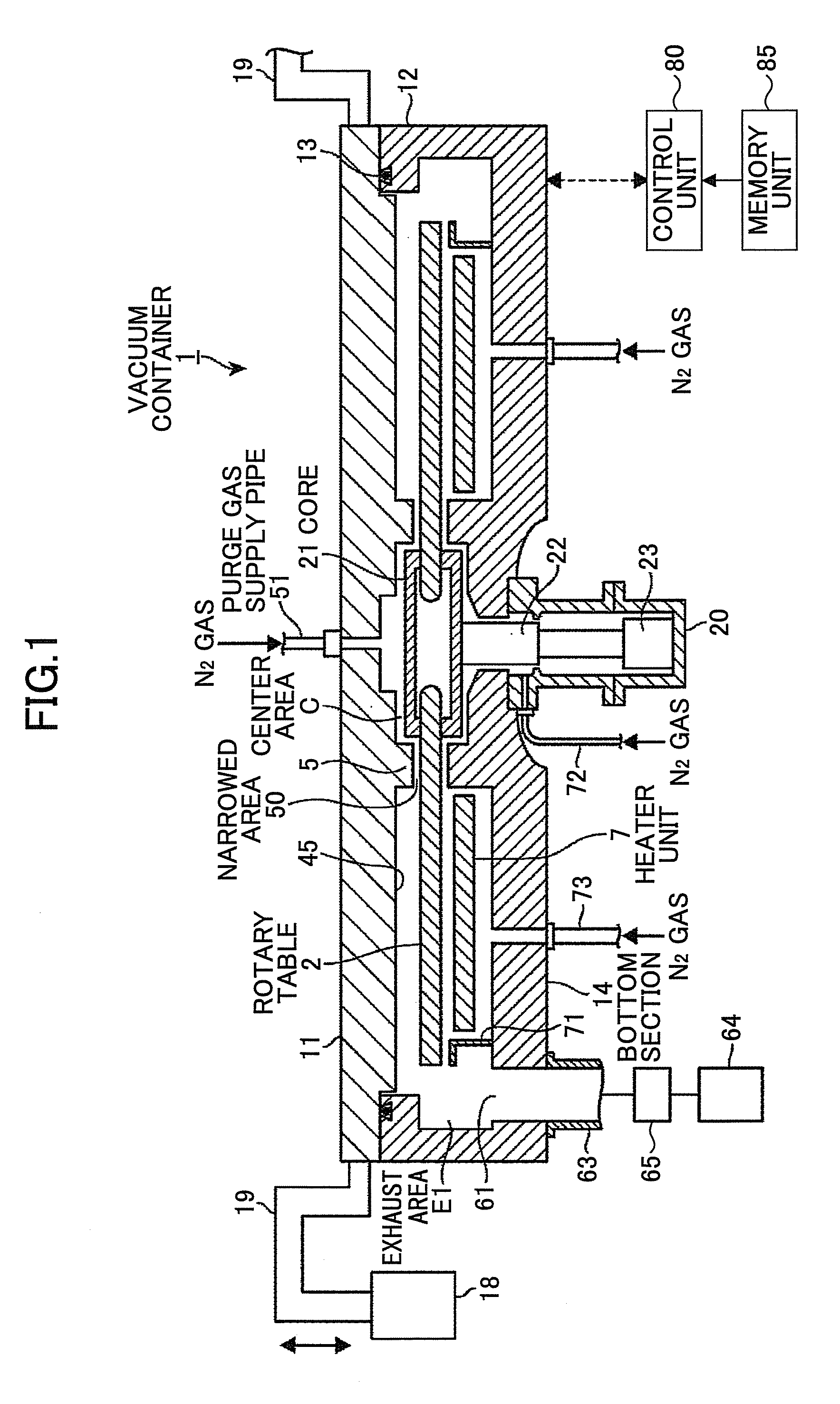
[0069]A film deposition apparatus according to a first embodiment of the present invention includes a vacuum container 1 having a generally flat circular shape and a rotary table 2 situated in the vacuum container 1 with a rotation center thereof at a general center of the vacuum container 1, as illustrated in FIG. 1 through FIG. 3. The vacuum container 1 includes a container 12 having a general cup shape to accommodate the rotary table 2 and a top panel 11 having a disc shape to hermetically seal the top opening of the container 12. An opening-&-closing mechanism 18 for lifting and lowering the top panel 11 is provided at the exterior of the vacuum container 1 as illustrated in FIG. 1. As illustrated in FIG. 3, lifting shafts 19 extending from the opening-&-closing mechanism 18 are situated at four points, for example, at equal intervals along the perimeter of ...


PUM

PropertyMeasurementUnit
diameteraaaaaaaaaa
diameteraaaaaaaaaa
distanceaaaaaaaaaa

Abstract

A film deposition apparatus includes a rotary table having a substrate placement area to support a substrate, a vacuum container including a container and a top panel, an open-and-close mechanism configured to open and close the top panel, reactant gas nozzles disposed through and supported by an outer wall of the container to be situated at different angular positions with respect to a rotation center of the rotary table to face areas in which the substrate placement area passes, the reactant gas nozzles having gas discharge ports arranged in radial directions to supply respective reactant gases to the wafer thereby to form respective process areas, a discharge gas supply unit situated at an angular position between the process areas to supply purge gas to form an isolation area that isolates atmospheres of the process areas from each other, and an exhaustion unit configured to exhaust atmosphere inside the vacuum container.

Description

BACKGROUND OF THE INVENTION[0001]1. Field of the Invention[0002]The disclosures herein generally relate to film deposition apparatuses, and particularly relate to a film deposition apparatus that forms a film on a substrate by supplying reactant gases through reactant gas nozzles in a vacuum container.[0003]2. Description of the Related Art[0004]A certain type of film deposition method used in semiconductor manufacturing processes supplies at least two types of reactant gases in sequence to a surface of a semiconductor wafer (hereinafter referred to as a “wafer”) serving as a substrate in vacuum atmosphere to form a film. This method repeats plural cycles, each of which causes a first reactant gas to be adsorbed to a surface of a substrate, for example, and then switches the supplied gas to a second reactant gas to form one or more layers of atoms or molecules through reaction of these two gases on the wafer surface. The repetition of cycles creates layers one over another thereby t...

Claims


Application Information

Patent Timeline
Patent Type & Authority Applications(United States)
IPC IPC(8): C23C16/50C23C16/00
CPCC23C16/402C23C16/45578C23C16/45551H01L21/205C23C16/4551H01L21/6719H01L21/67703
Inventor KATO, HITOSHIHONMA, MANABU
Owner TOKYO ELECTRON LTD
Why Eureka
Try Eureka