Variable Compression Ratio Apparatus

Inactive Publication Date: 2010-06-03
HYUNDAI MOTOR CO LTD
View PDF5 Cites 24 Cited by
  • Summary
  • Abstract
  • Description
  • Claims
  • Application Information

AI Technical Summary

Benefits of technology

[0018]In various aspect of the present invention, the variable compression ratio apparatus includes a connecting rod, a pin link, a slot link having a control slot, and a driving unit to be mounted in the cr

Problems solved by technology

However, in the conventional variable compression ratio apparatus having a multi-link type of control means, a journal portion for mounting the

Method used


Image

  • Variable Compression Ratio Apparatus
  • Variable Compression Ratio Apparatus
  • Variable Compression Ratio Apparatus

Examples


Embodiment Construction

[0031]Reference will now be made in detail to various embodiments of the present invention(s), examples of which are illustrated in the accompanying drawings and described below. While the invention(s) will be described in conjunction with exemplary embodiments, it will be understood that present description is not intended to limit the invention(s) to those exemplary embodiments. On the contrary, the invention(s) is / are intended to cover not only the exemplary embodiments, but also various alternatives, modifications, equivalents and other embodiments, which may be included within the spirit and scope of the invention as defined by the appended claims.

[0032]The various embodiments of the present invention will be described more fully hereinafter with reference to the accompanying drawings.

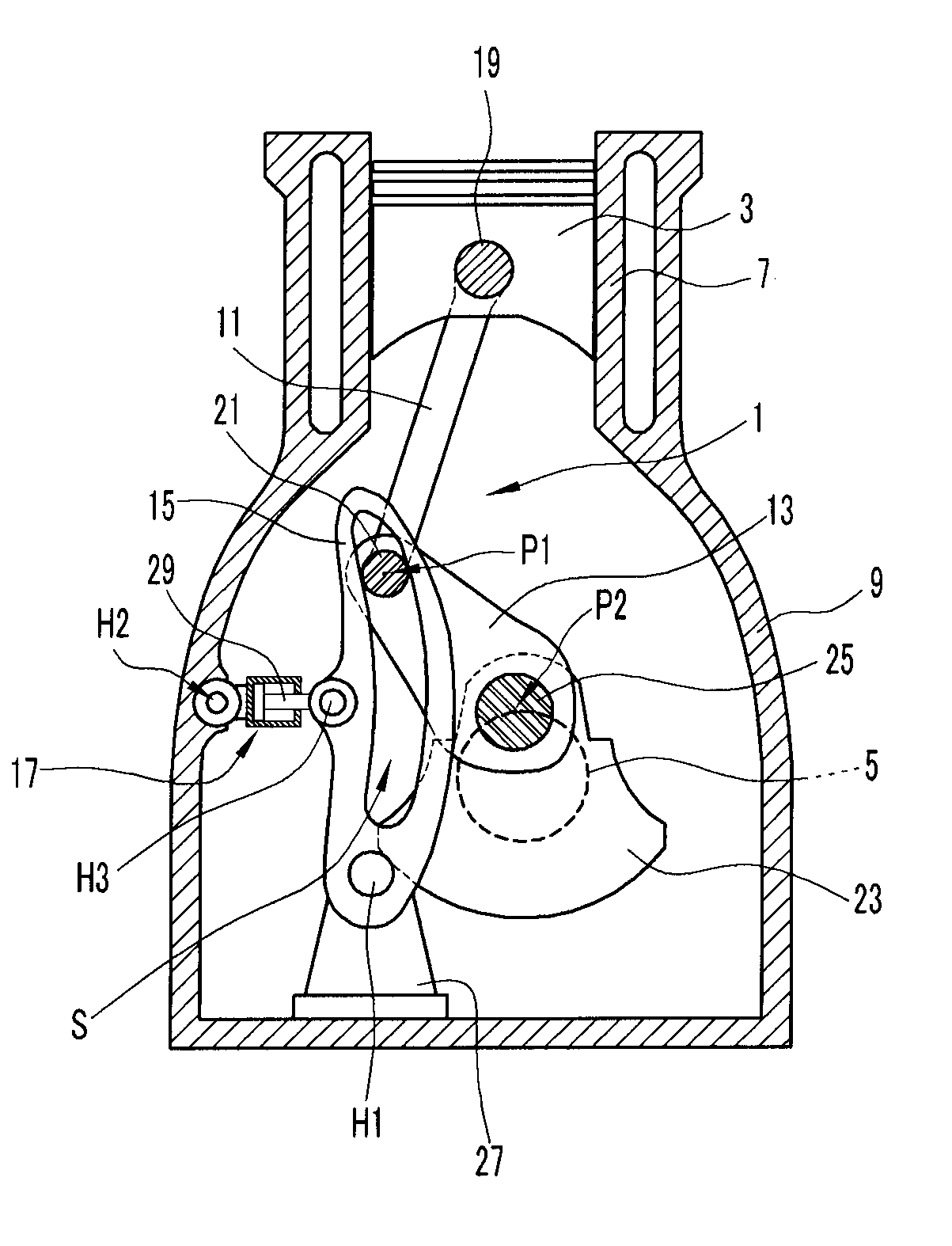
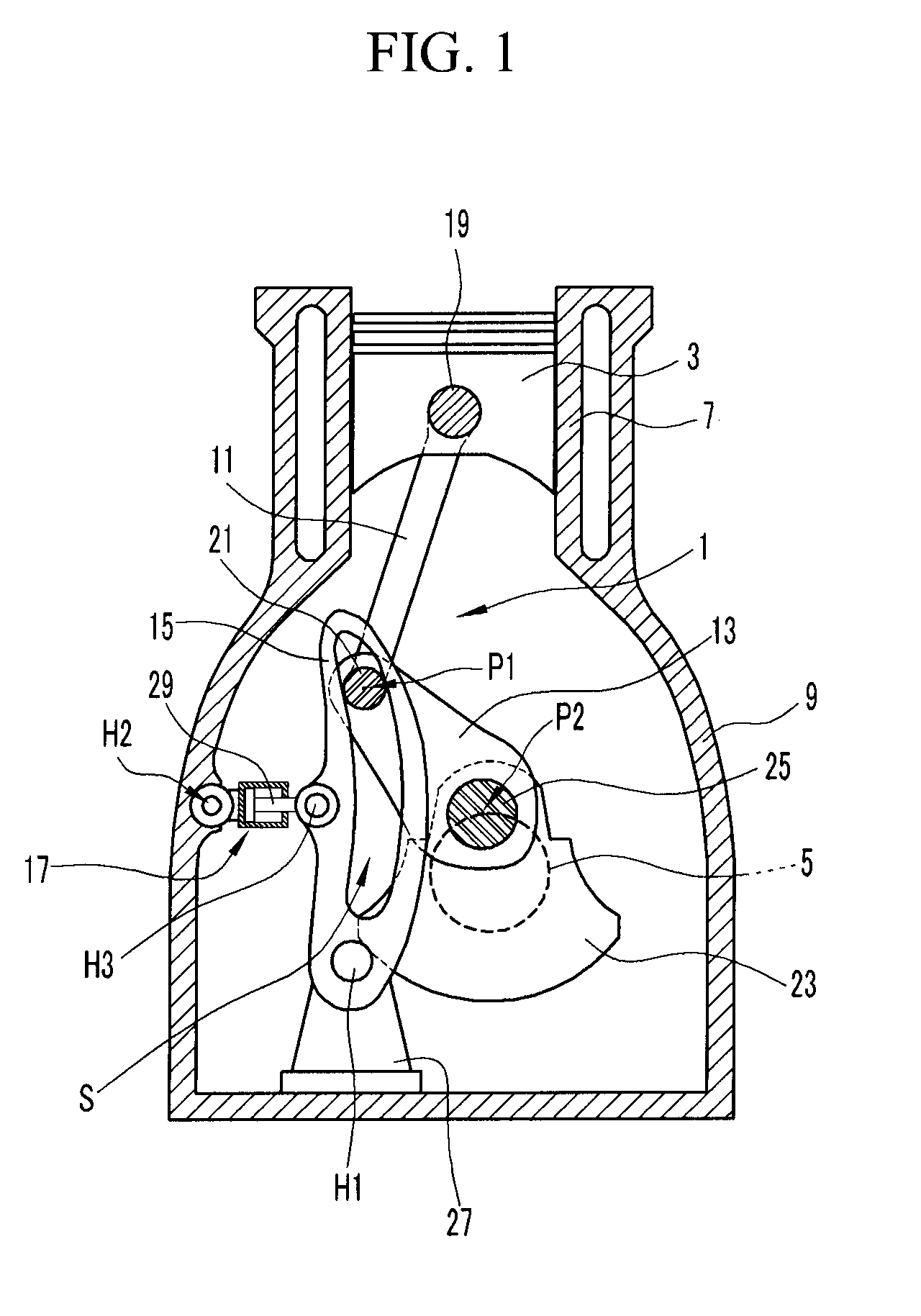
[0033]FIG. 1 is a schematic diagram showing the crankcase of an engine in which an exemplary variable compression ratio apparatus according to the present invention is applied.

[0034]As shown in FI...


PUM


Abstract

A variable compression ratio apparatus for varying a compression ratio, may include a connecting rod that is connected to a piston to take a combustion force; a pin link, one end of which is eccentrically connected to a crankshaft and the other end of which is pivotally connected to the connecting rod to form a connection portion therebetween; a slot link including a control slot to receive and guide the connection portion along the control slot; and a driving unit coupled to the slot link and configured to move the control slot to control a position of the connection portion.

Description

CROSS-REFERENCE TO RELATED APPLICATION[0001]The present application claims priority to Korean Patent Application No. 10-2008-0121487 filed on Dec. 2, 2008, the entire contents of which are incorporated herein for all purposes by this reference.BACKGROUND OF THE INVENTION[0002]1. Field of the Invention[0003]The present invention relates to a variable compression ratio apparatus. More particularly, the present invention relates to a variable compression ratio apparatus that varies the compression ratio of a mixed gas inside a combustion chamber according to driving conditions of an engine.[0004]2. Description of Related Art[0005]A variable compression ratio (VCR) apparatus varies the compression ratio of a mixed gas corresponding to operating conditions of an engine. According to the variable compression ratio apparatus, the compression ratio of the mixed gas is raised to decrease fuel consumption in a low load condition of the engine, and the compression ratio of the mixed gas is low...

Claims


Application Information

Patent Timeline
IPC IPC(8): F02D15/02
CPCF02B75/048Y02T10/12F02D15/02F02B75/04
Inventor CHO, MYUNG RAELEE, HONG WOOKKIM, WOO TAEKIM, WON GYUCHO, JIN WOO
Owner HYUNDAI MOTOR CO LTD
Why Eureka
Try Eureka