
Material dispensing system and method for making same

a technology of material dispensing system and material dispensing method, which is applied in the direction of liquid transferring device, pliable tubular container, electric/magnetic/electromagnetic heating, etc., can solve the problems of weakening the fixation point, and reducing the service life of the bag

Active Publication Date: 2010-06-03
THE PROCTER & GAMBLE COMPANY
View PDF3 Cites 55 Cited by
  • Summary
  • Abstract
  • Description
  • Claims
  • Application Information

AI Technical Summary

Benefits of technology

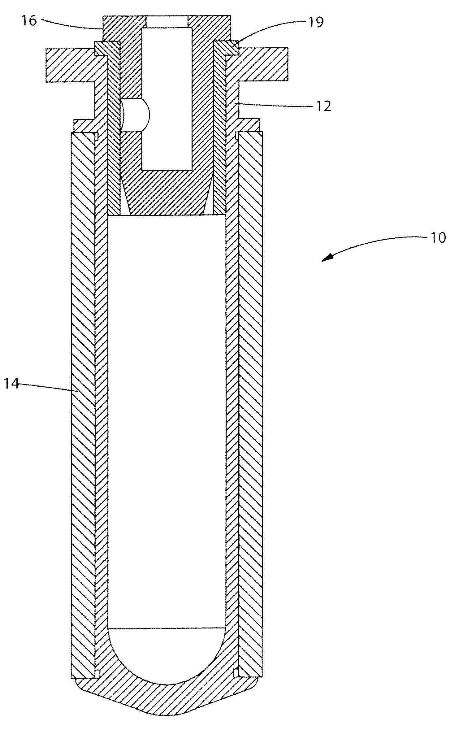
[0047]An exemplary personal care product 200 is shown in FIGS. 14 and 15. The product includes an outer package 210 defined by a shaped container 212 and overcap 214. A material dispensing system 216 is disposed within container 212, which includes a bag 218 filled with a flowable composition 219 and a stretched band 220 surrounding bag 218. An actuator 222 is positioned on container 212 and includes a flow path 224 defined partially by a tube 226. Tube 226 is connected to an elastically deformable valve member 228. Downward displacement of tube 226 elongates valve member 228 sufficiently to allow a volume of composition 219 to travel into

Problems solved by technology

Without intending to be bound by theory, it is believed that opaque rubber materials may cause difficulties when heating the polymeric perform through the elastically deformable band.
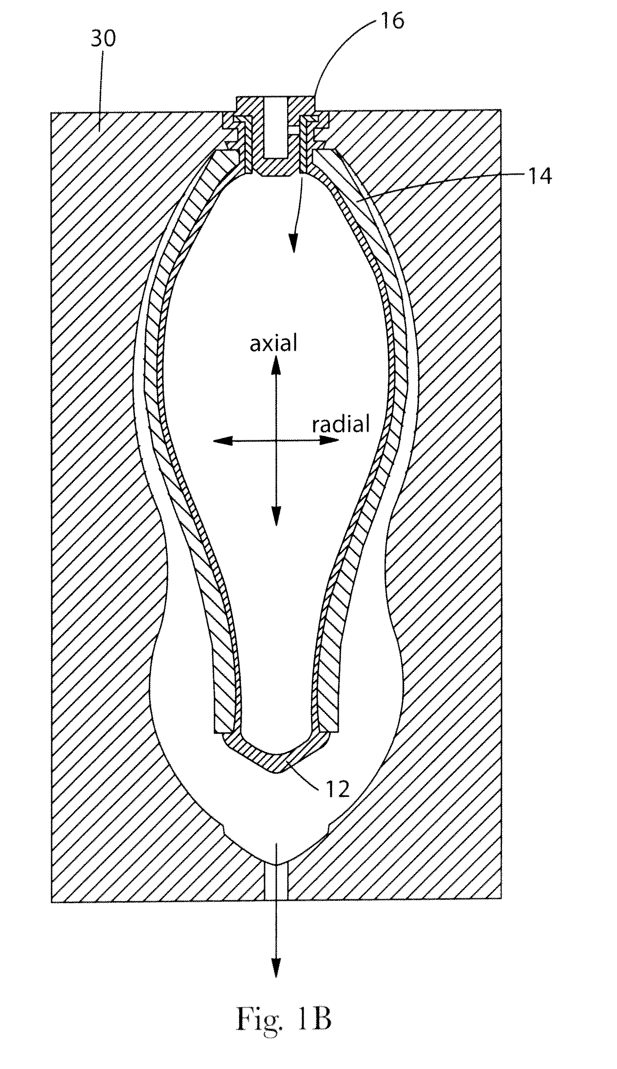
A significant amount of potential energy is generated with the band while the bag is formed which can collapse the recently formed bag very quickly if there is no regulation on the internal pressure exhaustion.
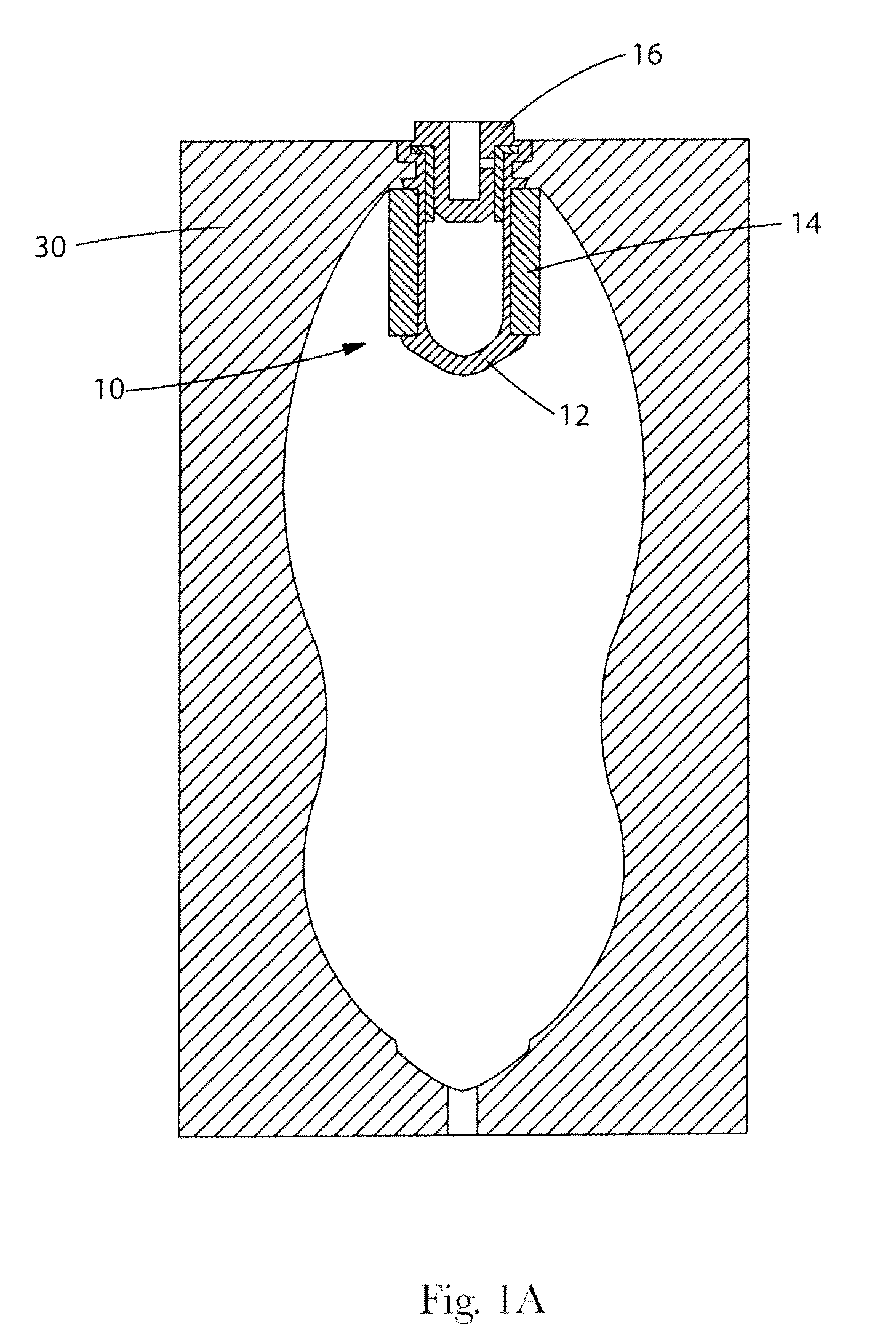
Applicant has discovered that a rapid exhaustion of internal air pressure which lead to a contraction of the outer band that rapidly collapse the inner bag immediately after blow molding process or before the bag material is sufficiently cure or cool down can potentially create defects in the bag or weaken the fixment points on the preform where the adhesive is anchoring to, when they exist, between the outer band and the bag.
And this potential energy can collapse the collapsible bag as the internal pressure is exhausted.
This approach can lead to a significant amount of product being trapped in the bottom portion of the bag as it contracts during use.

Method used


Image

  • Material dispensing system and method for making same
  • Material dispensing system and method for making same
  • Material dispensing system and method for making same

Examples


Embodiment Construction

[0026]The present invention may be understood more readily by reference to the following detailed description of illustrative and preferred embodiments. It is to be understood that the scope of the claims is not limited to the specific components, methods, conditions, devices, or parameters described herein, and that the terminology used herein is not intended to be limiting of the claimed invention. Also, as used in the specification, including the appended claims, the singular forms “a,”“an,” and “the” include the plural, and reference to a particular numerical value includes at least that particular value, unless the context clearly dictates otherwise. When a range of values is expressed, another embodiment includes from the one particular value and / or to the other particular value. Similarly, when values are expressed as approximations, by use of the antecedent basis “about,” it will be understood that the particular values form another embodiment. All ranges are inclusive and c...


PUM

PropertyMeasurementUnit
Fractionaaaaaaaaaa
Thicknessaaaaaaaaaa
Lengthaaaaaaaaaa

Abstract

Material dispensing systems and methods for make such systems are described. The material dispensing systems employ a collapsible container that is at least partially surrounded by an elastically deformable band. The band stretches as the container is filled with a flowable composition, thereby creating potential energy which can then be used to dispense the composition in lieu of a propellant and / or pressurized container.

Description

CROSS REFERENCE TO RELATED APPLICATION[0001]This application claims priority under 35 U.S.C. §119(e) to U.S. Provisional Application Ser. No. 61 / 107,905, filed Oct. 23, 2008 to John Geoffrey Chan et al.FIELD OF THE INVENTION[0002]The present invention is directed to material dispensing systems and methods for making the same. A unique valve is also disclosed that can optionally be used in both the described methods and / or in the final material dispensing systems. The present invention is further directed to packages and personal care products that employ the material dispensing systems described herein.BACKGROUND OF THE INVENTION[0003]Aerosol delivery systems have been widely used for several decades to deliver a variety of consumer goods, including, for example, personal care items, paint, foods, and home care products. These systems utilize volatile propellants to push the product out of the aerosol containers. Aerosol technology has gained favor for being both effective and relat...

Claims


Application Information

Patent Timeline
IPC IPC(8): B65D35/28B67D7/84B29C49/08B29C49/64B29C47/02
CPCB29B11/08B65D83/0061B29B2911/1402B29B2911/14026B29B2911/1404B29B2911/14066B29B2911/1408B29B2911/14113B29B2911/1412B29B2911/14133B29B2911/14166B29B2911/1424B29B2911/14313B29B2911/14326B29B2911/14333B29B2911/14593B29B2911/14646B29C49/06B29C49/221B29C49/6454B29C2049/2412B29C2049/2493B29K2007/00B29K2021/00B29K2023/065B29K2023/086B29K2023/12B29K2067/00B29K2077/00B29K2105/258B29L2031/7158B29B11/14B29C2949/3012B29C2949/3026B29C2949/3016B29C2949/3028B29C2949/28B29C2949/24B29C2949/22B29C2949/3042B29C2949/3064B29C2949/3032B29C2949/3092B29C2949/073B29C2949/0819B29C2949/072B29C2949/0811B29C2049/24304B29C49/071B29C2949/0715B29C2049/7831
Inventor CHAN, JOHN GEOFFREYO'BRIEN, LAWRENCE EDWARD
Owner THE PROCTER & GAMBLE COMPANY
Learn More