Copper, copper alloy, and manufacturing method therefor

a manufacturing method and technology of copper alloy, applied in the direction of metal rolling arrangement, etc., can solve the problems of reduced ductility, low ductility, and ductility decline, and achieve the effect of enhanced ductility and preferable bending properties

Inactive Publication Date: 2008-11-13
JX NIPPON MINING & METALS CORP
View PDF1 Cites 2 Cited by
  • Summary
  • Abstract
  • Description
  • Claims
  • Application Information

AI Technical Summary

Benefits of technology

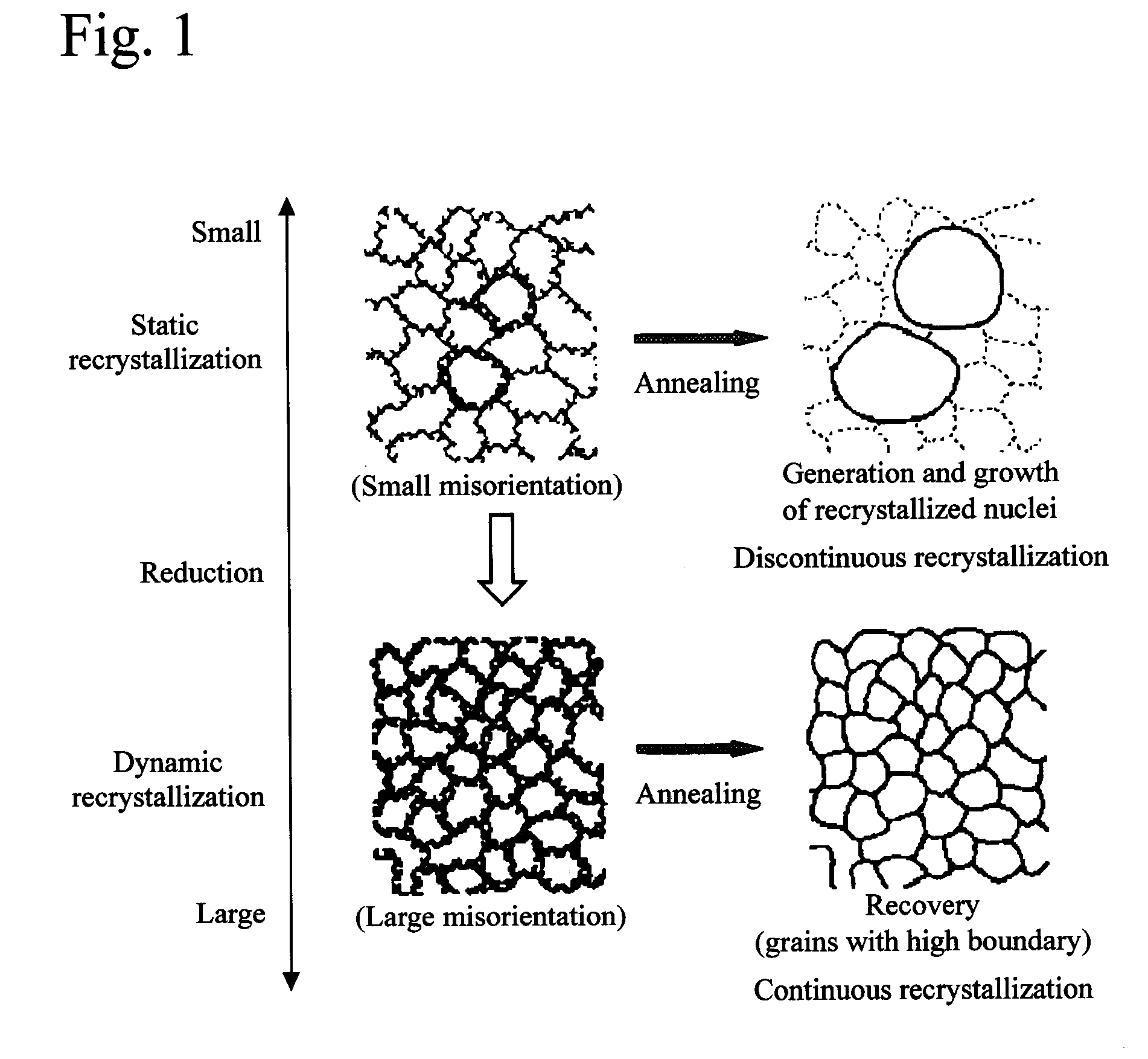
[0017]In order to obtain a favorable bending properties in a material subjected to final cold rolling alone, a high ductility is essential. In order to obtain the favorable bending properties not causing cracking in the bent portion, a fracture elongation in a tensile test is required to be 2% or more at a gauge length of 50 mm. In order to obtain a rupture elongation of 2% or more in the state of final cold rolling, the grain size after final cold rolling must be 1 μm or less. Thus, sufficient elongation is obtained in the cold rolled state by decreasing the grain size, which is because dislocations are piled-up in the grain boundary when continuous recrystallized grains are formed, and a grain boundary structure of a non-equilibrium state is formed and a grain boundary sliding is expressed, thereby enhancing the ductility.
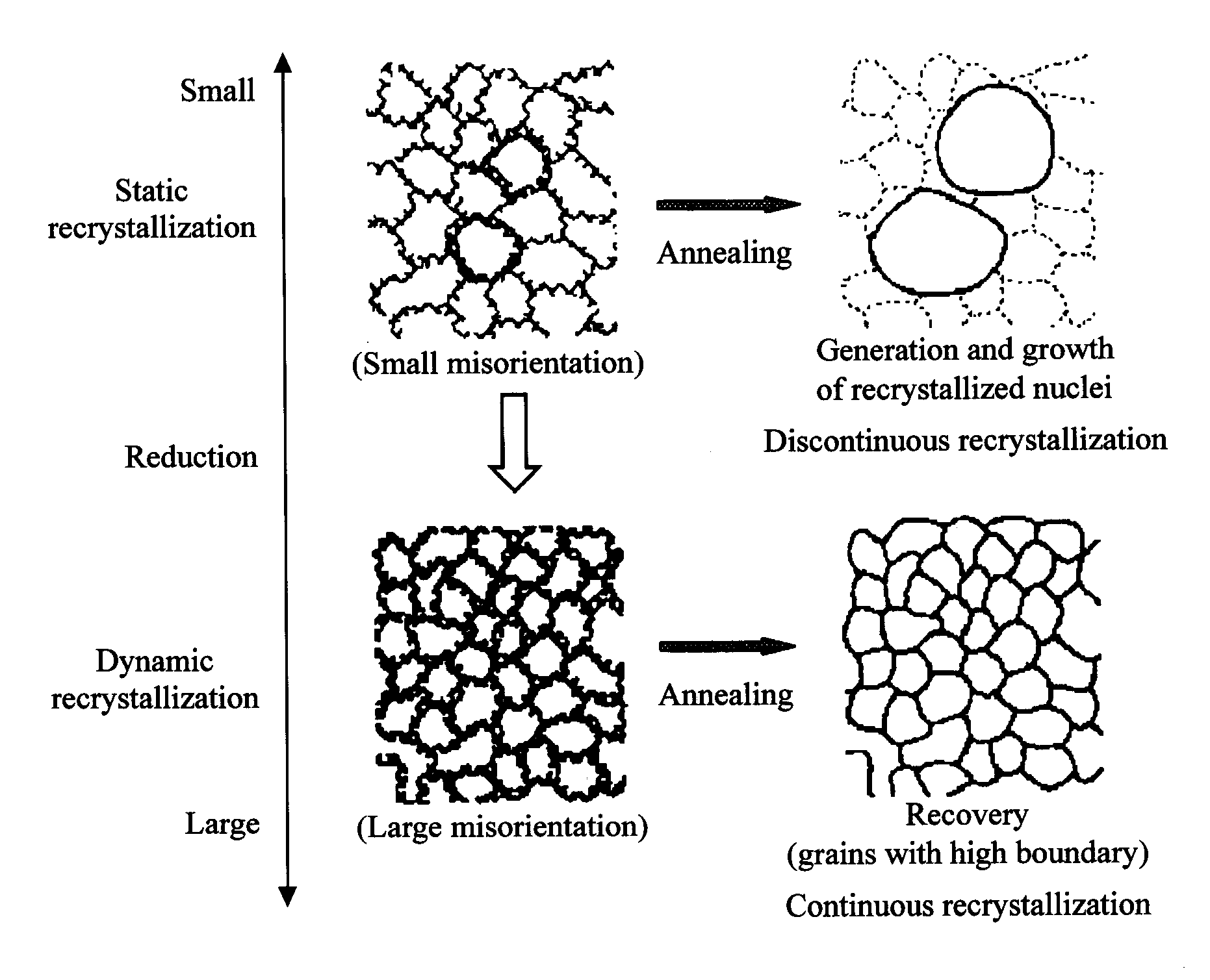
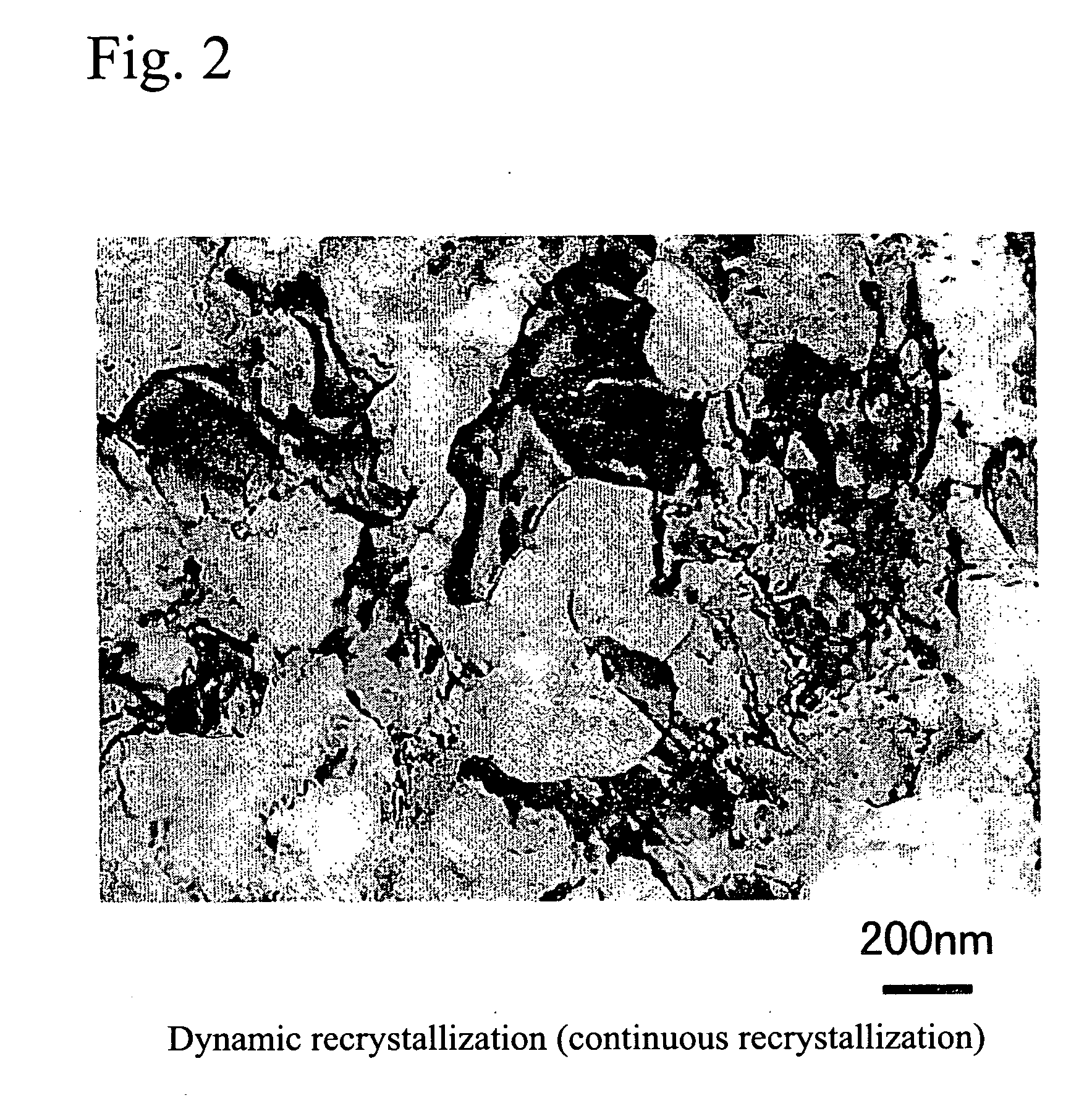
[0021]In contrast, by setting the extremely high cold rolling reduction, fine crystal grains are obtained. That is, at a very high cold rolling reduction, numerous regions locally shearing deformed occur in the matrix in the entire material and thus subgrain structures greatly grow. As a result, as shown in FIG. 1, dislocations are introduced in order to compensate the large misorientation between the matrix and the subgrain, and they are piled-up in the grain boundary. In this case, crystal grain boundaries having a large misorientation of 15° or more (high angle grain boundary) are generated. That is, the subgrain structure which has been initially a substructure of crystal grains is directly formed as crystal grains. In this case, the crystal grain boundary is largely different from the case of the static recrystallization, and there is no linearity in the grain boundary, and it is a feature that a crystal grain boundary mainly composed of curved portions is formed. This dynamic continuous recrystallization is mostly formed in cold rolling. It is also known that a clearer high angle grain boundary is grown by annealing at intentional low temperatures and bringing it into an ordinary recovery regime. In this case, it is found that the ductility is further enhanced as described below.
[0023]When the material after final cold rolling is further annealed for stress relief, the ductility is enhanced, and a further preferable bending properties are obtained. As annealing conditions, it is necessary to set adequate annealing conditions to such an extent that the product value will not be lost due to extreme decline of strength. The annealing condition differs with the alloy system, but by selecting an appropriate annealing condition in a temperature range of 80 to 500° C. and in a range of 5 to 60 minutes, an elongation of 6% or more may be easily obtained, and it is applicable to a severe bend forming.

Problems solved by technology

However, first of all, strength and ductility are inversely related to each other, and in each alloy system, when rolling is processed in order to increase the strength by work hardening, the ductility declines, and preferable workability is not obtained by rolling alone.
In this method, however, when the annealing temperature is lowered in order to reduce the grain size, non-crystallized grains remain in part, and there is substantially a limit to obtaining recrystallized grains of about 2 to 3 μm, and a technique for further reducing the grain sizes has been demanded.
Furthermore, by recrystallization alone, the strength level is usually low, and it is not practical, and therefore a certain rolling process is needed in a later step, which has led to reduction of ductility.
This process, however, causes lowered strength once obtained in the rolling process, and sufficient ductility is not obtained after stress relief annealing, and it was difficult to satisfy the recent extremely severe demand for bending deformation performance.
In these processing methods, however, a mass quantity sufficient to be used as materials for electronic devices cannot be manufactured, and there are not suited to industrial production.

Method used


Image

  • Copper, copper alloy, and manufacturing method therefor
  • Copper, copper alloy, and manufacturing method therefor
  • Copper, copper alloy, and manufacturing method therefor

Examples


embodiments

[0028]Effects of the invention are more specifically described below by referring to preferred embodiments. First, using electric copper or oxygen-free copper as material, a specified amount of the material was put in a vacuum melting furnace, together with other additive elements, if necessary, and ingots of the chemical composition shown in Tables 1 to 3 were obtained by casting at the molten metal temperature of 1250° C. Table 1 shows the compositions of Cu—Ni—Si alloys, Table 2 shows the Cu—Cr—Zr alloys, and Table 3 shows other copper alloys.

TABLE 1Cu—Ni—Si alloyFinal Rolling ConditionOriginalFinalProduct PropertiesChemical compositionPlatePlateColdGrainTensileRuptureBendingConduc-Cu andThicknessThicknessRollingSizeStrengthElongationProper-tivityNiSiImpurities(mm)(mm)Reduction(μm)(MPa)(%)ties(% IACS)Example of13.020.67Balance3.300.153.10.208203.7◯48Invention22.750.59Balance3.800.153.20.158103.8◯5033.180.62Balance3.650.153.20.158304.5◯4943.300.70Balance3.400.153.10.208203.8◯4852....


PUM

PropertyMeasurementUnit
grain sizeaaaaaaaaaa
elongationaaaaaaaaaa

Abstract

Copper and copper alloy comprises: a structure having fine crystal grains with grain size of 1 μm or less after a final cold rolling with a reduction η, wherein η is expressed in the following formula and satisfying η≧3; and an elongation of 2% or more in a tensile test.η=ln(T0 / T1)T0: plate thickness before rolling, T1: plate thickness after rolling.

Description

CROSS-REFERENCE TO RELATED APPLICATION[0001]This application is a continuation of U.S. patent application Ser. No. 10 / 105,454, filed Mar. 26, 2002, which parent application is incorporated herein by reference in its entirety.BACKGROUND OF THE INVENTION[0002]1. Field of the Invention[0003]The present invention relates to copper and to copper alloys having fine crystal grains, and relates to a manufacturing method therefor, and more particularly, the resent invention relates to a technology for enhancing the characteristics in bending or other working when used for electronic devices such as terminals, connectors, and lead frames for semiconductor integrated circuits.[0004]2. Description of the Related Art[0005]Recently, electronic devices such as terminals and connectors and their parts are reduced in size and thickness, and copper and copper alloy used as materials thereof are demanded to have high strength. In terminal and connector material, the contact pressure must be increased ...

Claims


Application Information

Patent Timeline
Patent Type & Authority Applications(United States)
IPC IPC(8): C22C9/06C22C9/00B21B3/00C22F1/08
CPCB21B3/00B21B2003/005C22F1/08C22C9/00
Inventor TOMIOKA, YASUOMIYAKE, JUNJI
Owner JX NIPPON MINING & METALS CORP
Why Eureka
Try Eureka