Permanent-magnet rotary electric machine

Active Publication Date: 2010-06-03
NIDEC SERVO CORP
View PDF17 Cites 11 Cited by
  • Summary
  • Abstract
  • Description
  • Claims
  • Application Information

AI Technical Summary

Benefits of technology

[0011]In addition, adjacent rotor magnetic poles of the two rotor units have the same polarity in the rotary electric machine having the aforementioned structure. Thus, the rotary electric machine can use both effects provided by axially dividing a magnetic path in the whole rotor into two and thus shortening the magnetic-path length, and effects provided by magnetic fields which do not interfere with each other at the boundary between the two shortened magnetic paths. Moreover, the permeance vectors of the inductor teeth can be balanced, i.e., the sum

Problems solved by technology

Such a multiple rotor structure, however, cannot provide a sufficiently high torque with low vibration because of the problems related to the rotor and the stator.
First, the problems related to the rotor are described.
Moreover, the directions of interlinking magnetic fluxes from the rotor are opposite to each other around the non-magnetic disk, i.e., the boundary between two adjacent magnetic circuits, thus causing magnetic interfer

Method used


Image

  • Permanent-magnet rotary electric machine
  • Permanent-magnet rotary electric machine
  • Permanent-magnet rotary electric machine

Examples


first preferred embodiment

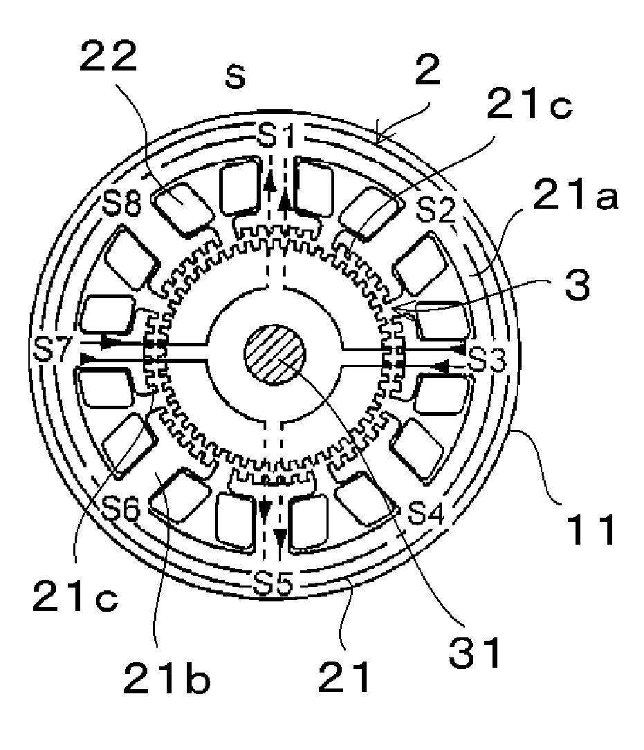
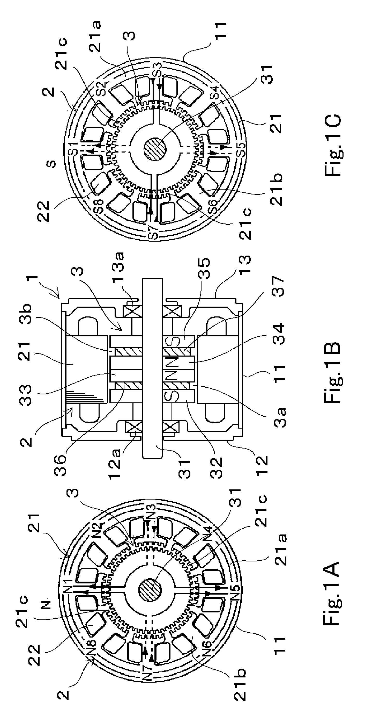
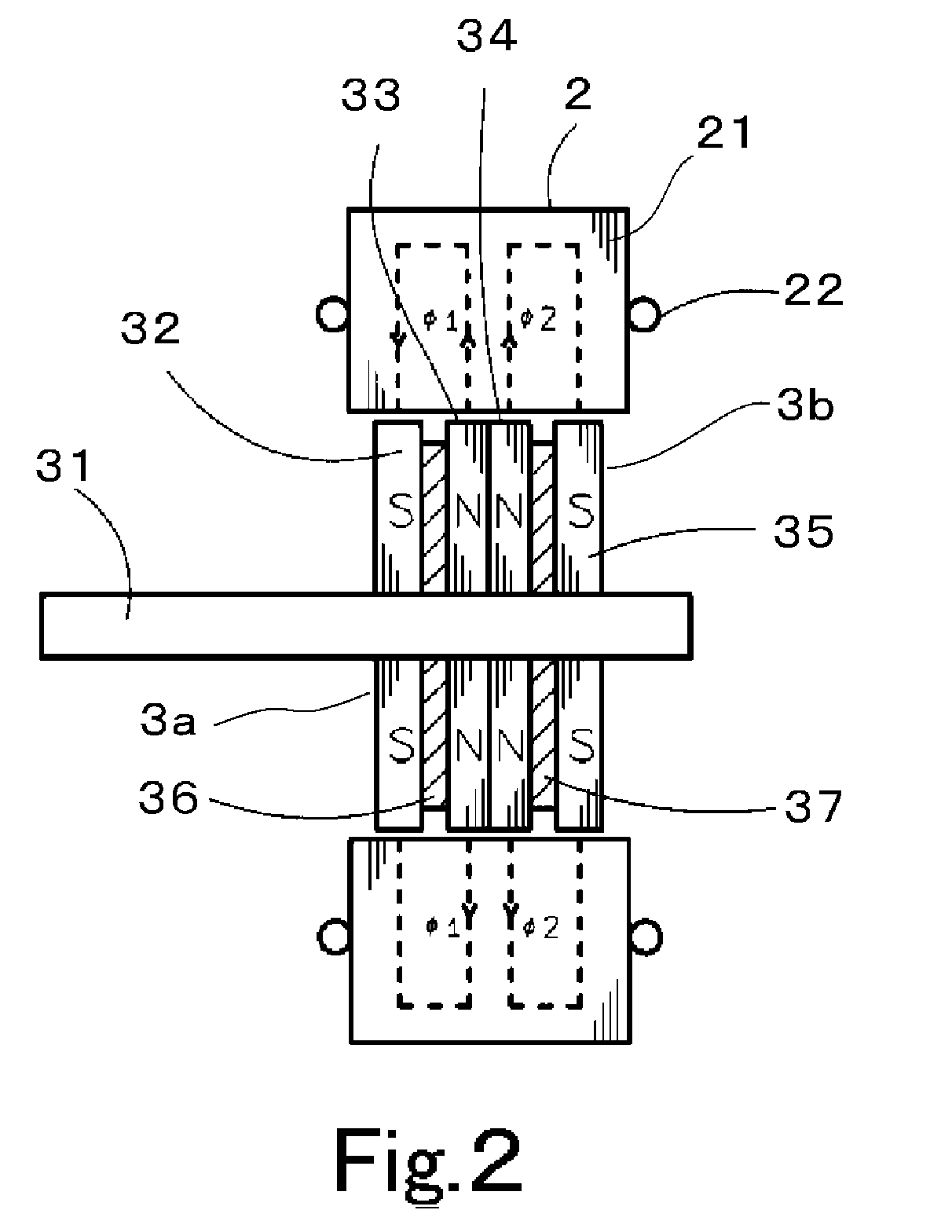
[0027]FIGS. 1A, 1B and 1C show a rotary electric machine according to a first preferred embodiment of the present invention. In this preferred embodiment, the rotary electric machine preferably is a stepper motor which includes a two-phase stator having 4m (m is an integer equal to or larger than 2) main poles and a rotor having two HB rotor units, where m=2. That is, the stator preferably has eight main poles, for example. FIGS. 1A and 1C are cross-sectional views of the rotary electric machine which are taken along a plane perpendicular to the rotation axis of the machine and seen from the north pole side and the south pole side, respectively. FIG. 1B is a cross-sectional view of the rotary electric machine of this preferred embodiment, taken along a plane parallel to the rotation axis.

[0028]The rotary electric machine of this preferred embodiment preferably includes a motor case 1 defined by a substantially cylindrical casing 11 and endplates 12 and 13 arranged at both ends of th...

second preferred embodiment

[0075]The second preferred embodiment of the present invention is now described referring to FIGS. 9 to 11. In the following description, the same reference signs as those in the first preferred embodiment are used for the same or similar components as / to those in the first preferred embodiment.

[0076]FIG. 9 shows six inductor teeth 21c′, for example, in a stator main pole 21b′ in this preferred embodiment. The six inductor teeth 21c′ are arranged at irregular pitches and the widths thereof are not all the same. As a typical two-phase, eight-main-pole HB type stepper motor, a stepper motor is widely used in which the number of magnetic teeth of a rotor is preferably 50, a step angle is preferably about 1.8°, and one revolution preferably corresponds to 200 steps, for example. In the stepper motor, when six inductor teeth are arranged at the tip of each of eight main poles, for example, the total number of the stator teeth in the stepper motor is 48, which is close to the total number...


PUM

PropertyMeasurementUnit
Lengthaaaaaaaaaa
Angleaaaaaaaaaa
Angleaaaaaaaaaa

Abstract

A permanent-magnet rotary electric machine preferably includes a stator and a rotor opposed thereto via an air gap. The stator includes a stator core having 4m (m is an integer equal to or larger than 2) main poles each having inductor teeth at a tip thereof. The rotor includes two rotor units adjacent to each other in the axial direction. Each rotor unit includes a pair of rotor magnetic poles and a permanent magnet arranged therebetween. The permanent magnets in the rotor are axially magnetized in opposite directions to each other. Each rotor magnetic pole has magnetic teeth on its outer periphery at a regular pitch. The rotor magnetic poles in each rotor unit are arranged such that the magnetic teeth of one rotor magnetic plate are offset by half a pitch from those of the other rotor magnetic pole, and the magnetic teeth of adjacent rotor magnetic poles are aligned with each other in the axial direction. The tooth pitch of the inductor teeth of each stator main pole is different from that of the magnetic teeth of the rotor magnetic pole to generate a fourth harmonic component of a permeance between the stator and the rotor zero.

Description

BACKGROUND OF THE INVENTION[0001]1. Field of the Invention[0002]The present invention relates to a permanent-magnet rotary electric machine such as, for example, a stepper motor, which includes a stator having 4m (where m is an integer equal to or larger than 2) main poles as winding cores and two hybrid permanent-magnet rotors concentrically arranged with the stator and close to the stator.[0003]2. Description of the Related Art[0004]Rotary electric machines such as stepper motors used in office machines are required to provide a high torque within a compact size, with low vibration.[0005]In a hybrid (hereinafter, simply referred to as “HB type”) stepper motor, a high torque can be achieved by increasing the axial thickness of a stator composed of a plurality of axially laminated plates. However, the motor diameter is determined in advance and the area of the surface of a permanent magnet of the motor from which magnetic fluxes exit is also determined. Thus, the magnetic fluxes are...

Claims


Application Information

Patent Timeline
IPC IPC(8): H02K37/04H02K15/03
CPCY10T29/49012H02K37/18
Inventor SAKAMOTO, MASAFUMIUNOKI, YOJIKOBAYASHI, TORU
Owner NIDEC SERVO CORP
Why Eureka
Try Eureka