
Residual gas analyzer

a gas analyzer and gas fitting technology, applied in the field of gas fitting analyzers, can solve the problems of inability to display analysis results, limited by the fitting position of the sensor unit, etc., and achieve the effect of convenient handling

Inactive Publication Date: 2010-06-03
HORIBA STEC CO LTD
View PDF4 Cites 5 Cited by
  • Summary
  • Abstract
  • Description
  • Claims
  • Application Information

AI Technical Summary

Benefits of technology

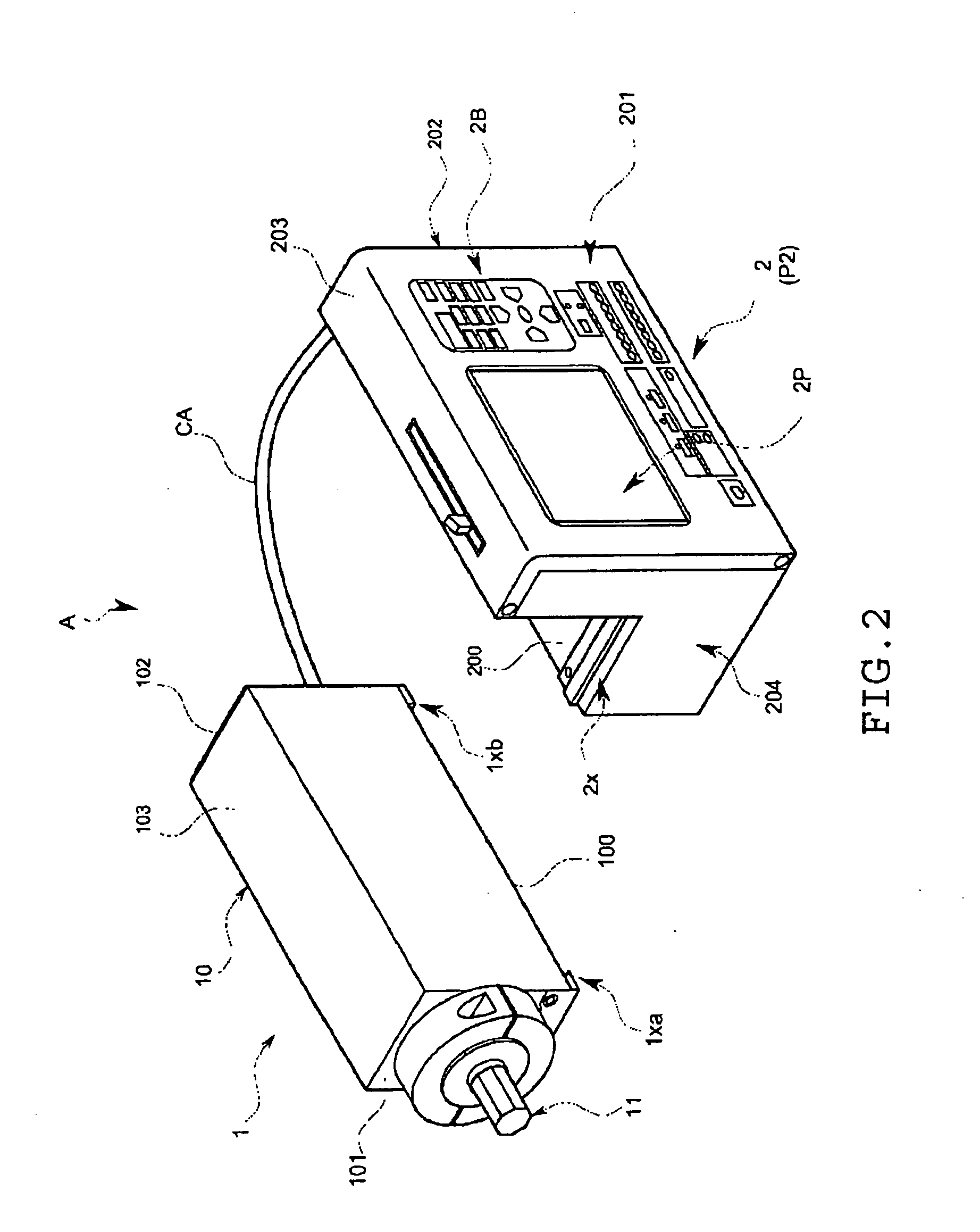
[0018]As described, regarding the residual gas analyzer according to the present invention, if the sensor unit is removed from the device main body, it can be arranged and used in the small area of the semiconductor equipment, which cannot contain the device as a whole. On the other hand, if the sensor unit is mounted on the device main body, the device can be independently used as a whole, and is therefore easy to handle. Also, the device does not require activation of an external device such as a personal computer to operate the sensor part, and therefore can be convenient.
[0019]That is, there can be provided the excellent gas analyzer, which can make a measurement with being suitably arranged even in the small area of the semiconductor equipment, or the like, and without an external personal computer, perform operations from the measurement to a display of a result of the measurement.

Problems solved by technology

However, in a conventional configuration, because the sensor unit and interface part are separate bodies, it is considered that the sensor unit can be arranged in a small area of the semiconductor equipment to make a measurement; however, the measurement can only be made with the sensor unit being cable-connected to the external personal computer, and is therefore virtually limited by a fitting position of the sensor unit.
Also, without the external personal computer, analysis results cannot even be displayed.

Method used


Image

  • Residual gas analyzer
  • Residual gas analyzer
  • Residual gas analyzer

Examples


Embodiment Construction

[0035]One embodiment of the present invention will hereinafter be described referring to the drawings.

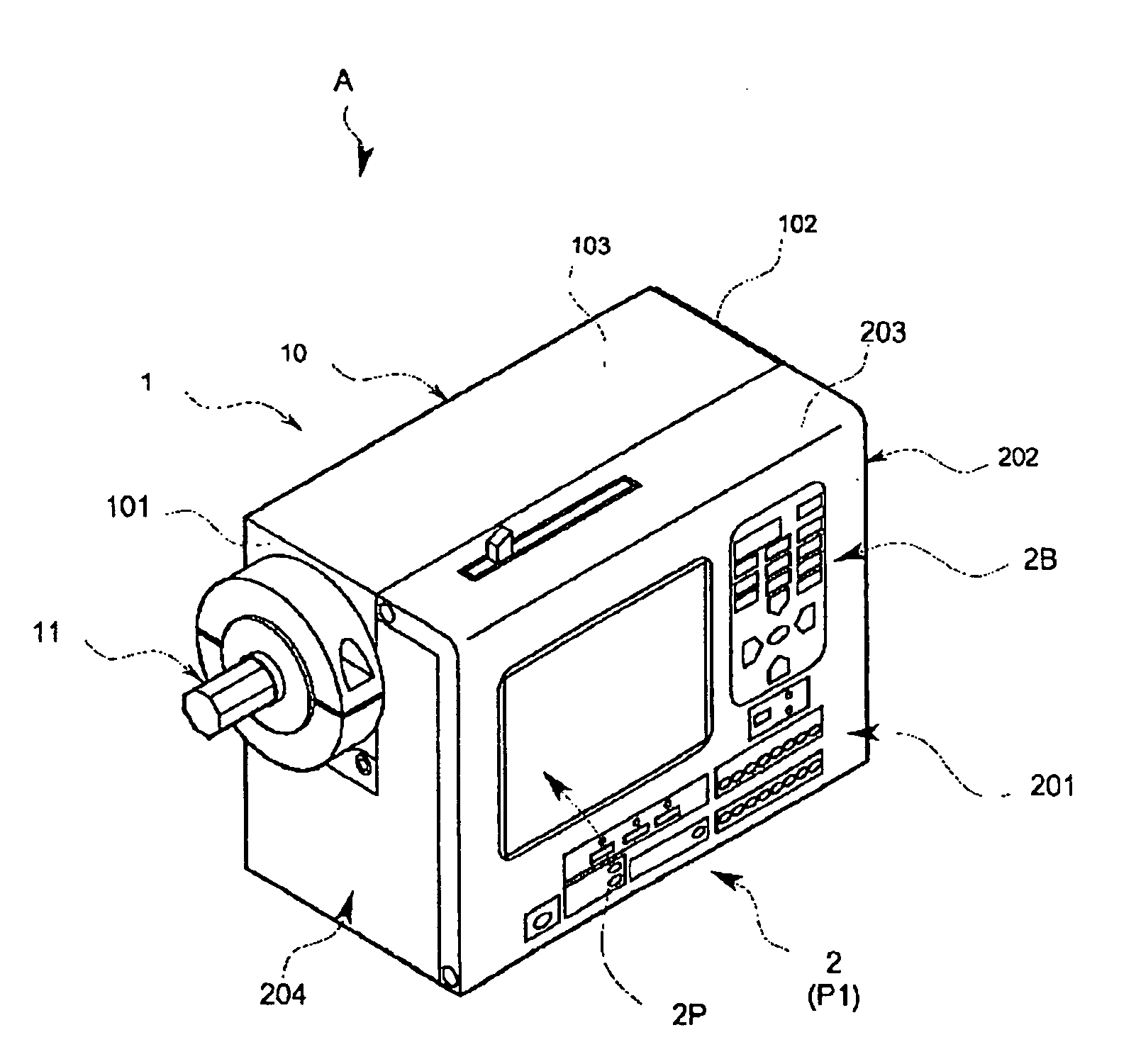
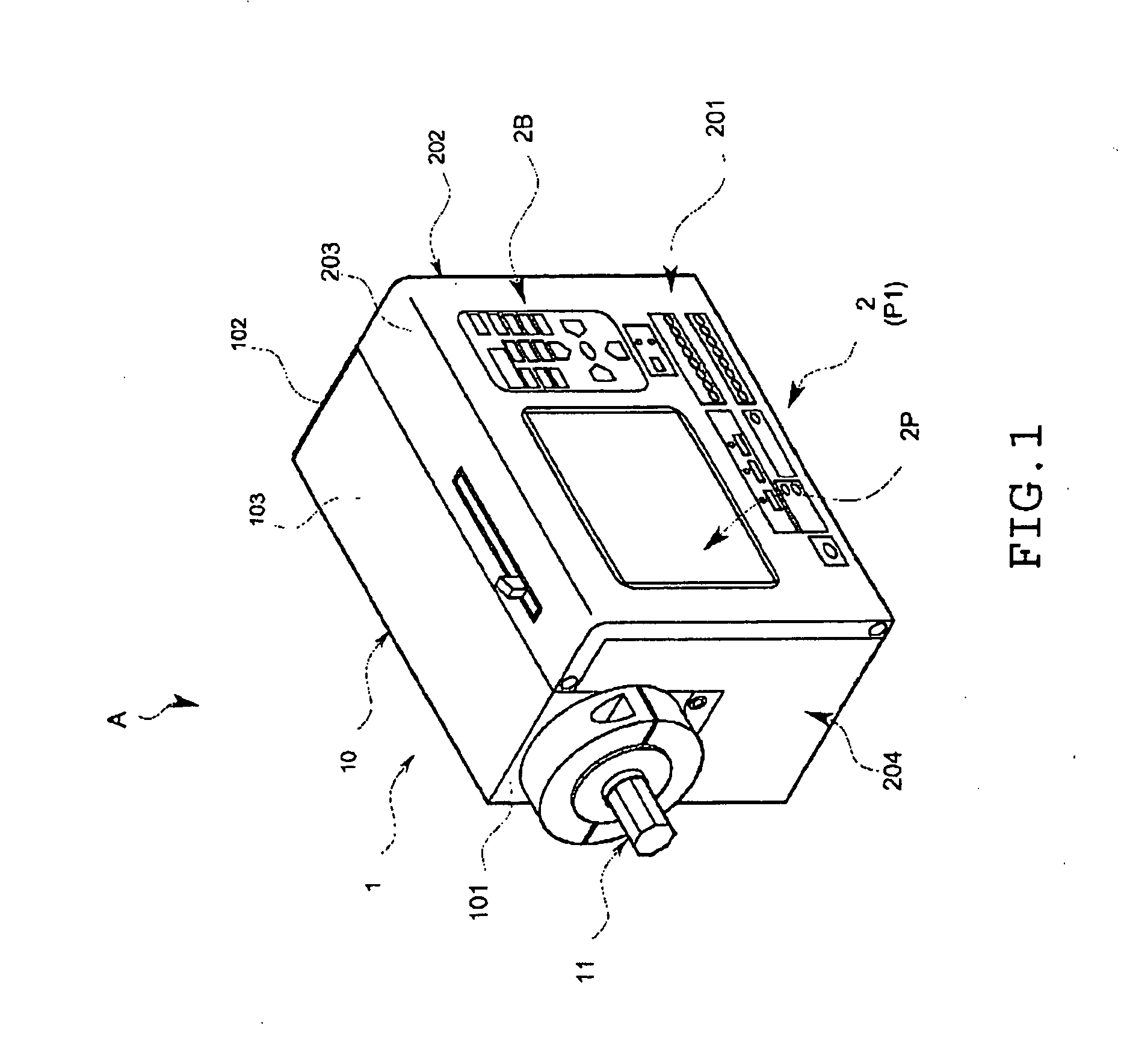
[0036]A residual gas analyzer A of the present embodiment is, as illustrated in FIGS. 1 to 8, configured to include: a sensor unit 1 integrally provided with a sensor part 11 for sensing a residual gas and a spectraconverter part 12 (not shown); and a device main body 2, which can be in a mounted status (P1) (see FIG. 1) where the sensor unit 1 is mounted or in a removed status (P2) (see FIG. 2) where the sensor unit 1 is removed. The respective parts are specifically described below.

[0037]The sensor unit is, as illustrated in FIG. 1 and the other drawings, configured to provide a sensor unit case 10 of a substantially rectangular parallelepiped shape with the sensor part 11, and the unshown spectraconverter part 12, power supply, and the like. Note that, in the present embodiment, a tip side of the sensor part 11 is projected from one side wall 101 of the sensor unit case 10. Also,...


PUM


Abstract

Provided is an excellent residual gas analyzer, which can perform measurement by being suitably arranged even in small areas, such as those in semiconductor equipments, and can perform measurement to display of measurement results without an external personal computer. The analyzer is provided with a sensor unit (1) having a sensor section (11) for detecting a residual gas; an operating section for receiving operation for controlling the sensor section (11); a residual gas analysis processing section for processing analysis of the residual gas based on the output from the sensor section (11); and an analysis processing result screen display section for displaying on a screen the analysis processing results obtained from the residual gas analysis processing section. The analyzer is also provided with a device main body (2) which can be in a mounted status (P1) wherein the sensor unit (1) is mounted or in a removed status (P2) wherein the sensor unit is removed.

Description

FIELD OF THE INVENTION[0001]The present invention relates to a residual gas analyzer used for a residual gas analysis or the like in a chamber of a semiconductor equipment or the like.BACKGROUND ART[0002]In recent years, as semiconductor devices are increasingly integrated and functionalized, deposition and etching processes are rapidly switched to corresponding dry processes.[0003]To stably provide high quality products, real-time control is crucial to accurately grasp a state inside a chamber and keep a process in an optimum state. For this reason, a residual gas analyzer (RGA) is strongly desired.[0004]Specifically, it is known that this type of residual gas analyzer is configured to include: a sensor unit integrally provided with a sensor part including an ion source, a mass analyzing part, and a detection part, and a spectraconverter part; and an interface part that is provided between the sensor unit and an external personal computer and cable-connected to them (see, for examp...

Claims


Application Information

Patent Timeline
IPC IPC(8): G01N27/62
CPCH01J49/00G01N27/62G01N27/623H01J49/26
Inventor IKEDA, TORUAOKI, JUNJITAKIJIRI, KOTARO
Owner HORIBA STEC CO LTD
Learn More