
Wireless Transmission Apparatus, Wireless Reception Apparatus and Block Construction Method

a technology of wireless reception and transmission apparatus, which is applied in the direction of digital transmission, multiple modulation transmitter/receiver arrangement, pulse technique, etc., can solve the problems of inter-symbol interference, and distortion of the spectra of signals that propagate through such a channel and are received, so as to prevent deterioration of error rate performance and reduce data rate

Inactive Publication Date: 2010-06-03
PANASONIC CORP
View PDF4 Cites 23 Cited by
  • Summary
  • Abstract
  • Description
  • Claims
  • Application Information

AI Technical Summary

Benefits of technology

[0010]The present invention makes it possible to prevent deterioration of error rate performance without decreasing the data rate, in mobile communication where precoding is combined with FDE.

Problems solved by technology

If such wideband transmission is performed in mobile communication, it is known that a communication channel becomes a frequency selective channel formed with a plurality of paths of varying delay times. Therefore, with wideband transmission in mobile communication, preceding symbols interfere with subsequent symbols, causing inter-symbol interference and deteriorating error rate performance.
Further, in a frequency selective channel, channel transfer functions fluctuate in frequency bands and therefore the spectra of signals that propagate through such a channel and are received are distorted.
However, the combination of THP with FDE has characteristics of deteriorating error rate performance of symbols near the head of a received block subjected to FDE.

Method used


Image

  • Wireless Transmission Apparatus, Wireless Reception Apparatus and Block Construction Method
  • Wireless Transmission Apparatus, Wireless Reception Apparatus and Block Construction Method
  • Wireless Transmission Apparatus, Wireless Reception Apparatus and Block Construction Method

Examples


Embodiment Construction

[0017]Hereinafter, an embodiment of the present invention will be explained in detail with reference to the accompanying drawings.

[0018]With the present embodiment, a radio transmitting apparatus transmits single carrier signals subjected to THP, to a radio receiving apparatus, and the radio receiving apparatus performs FDE of the single carrier signals.

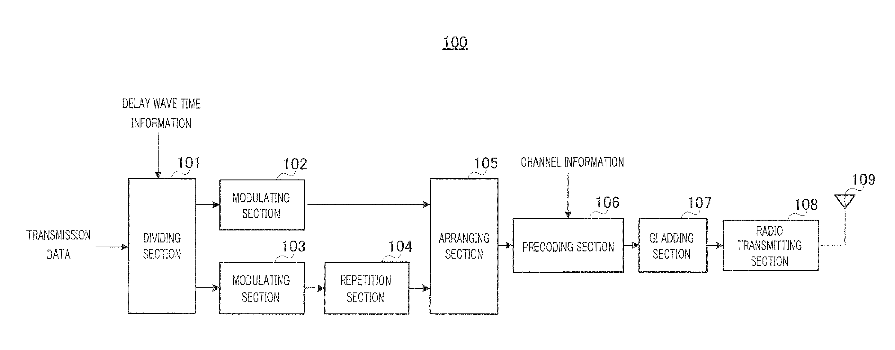
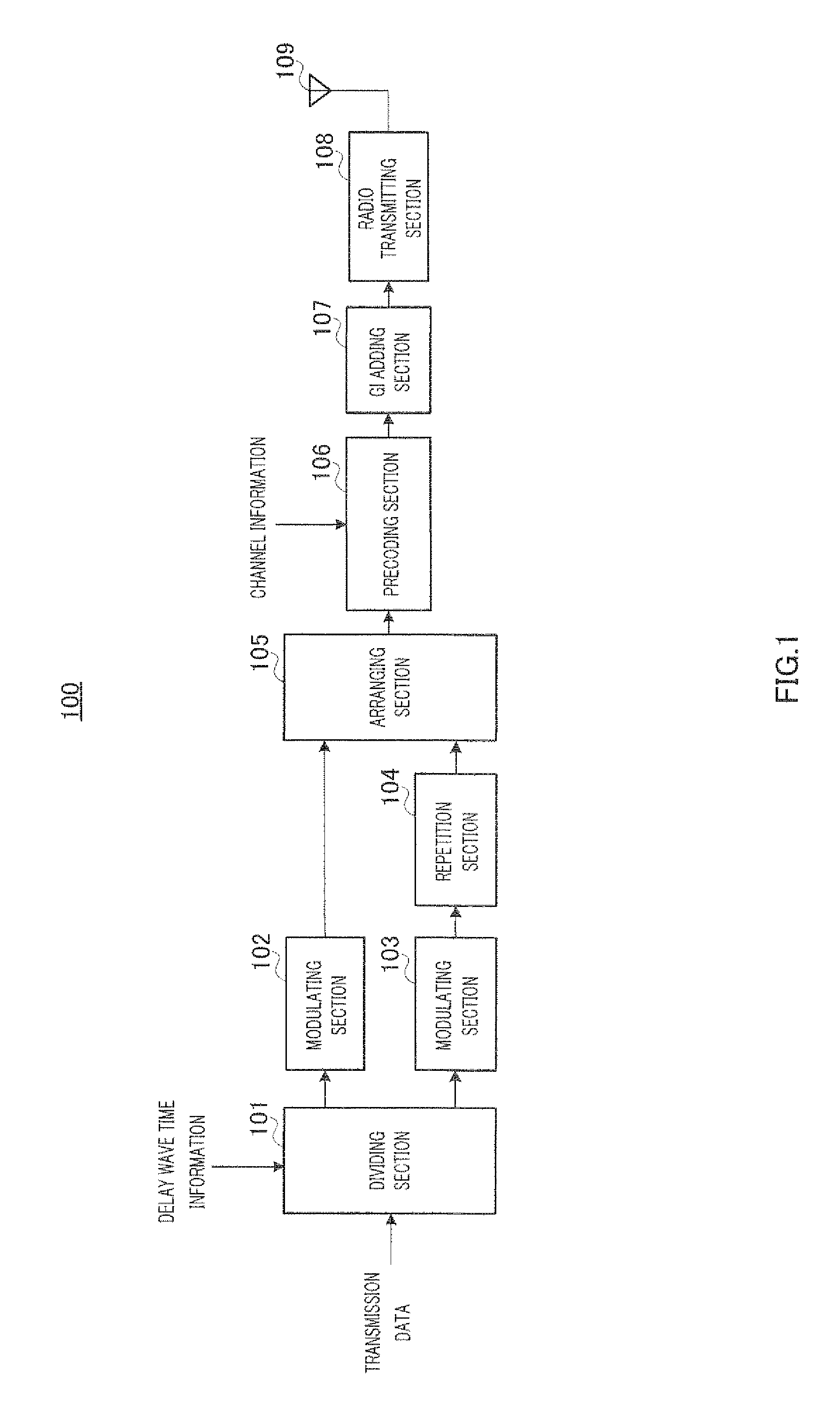
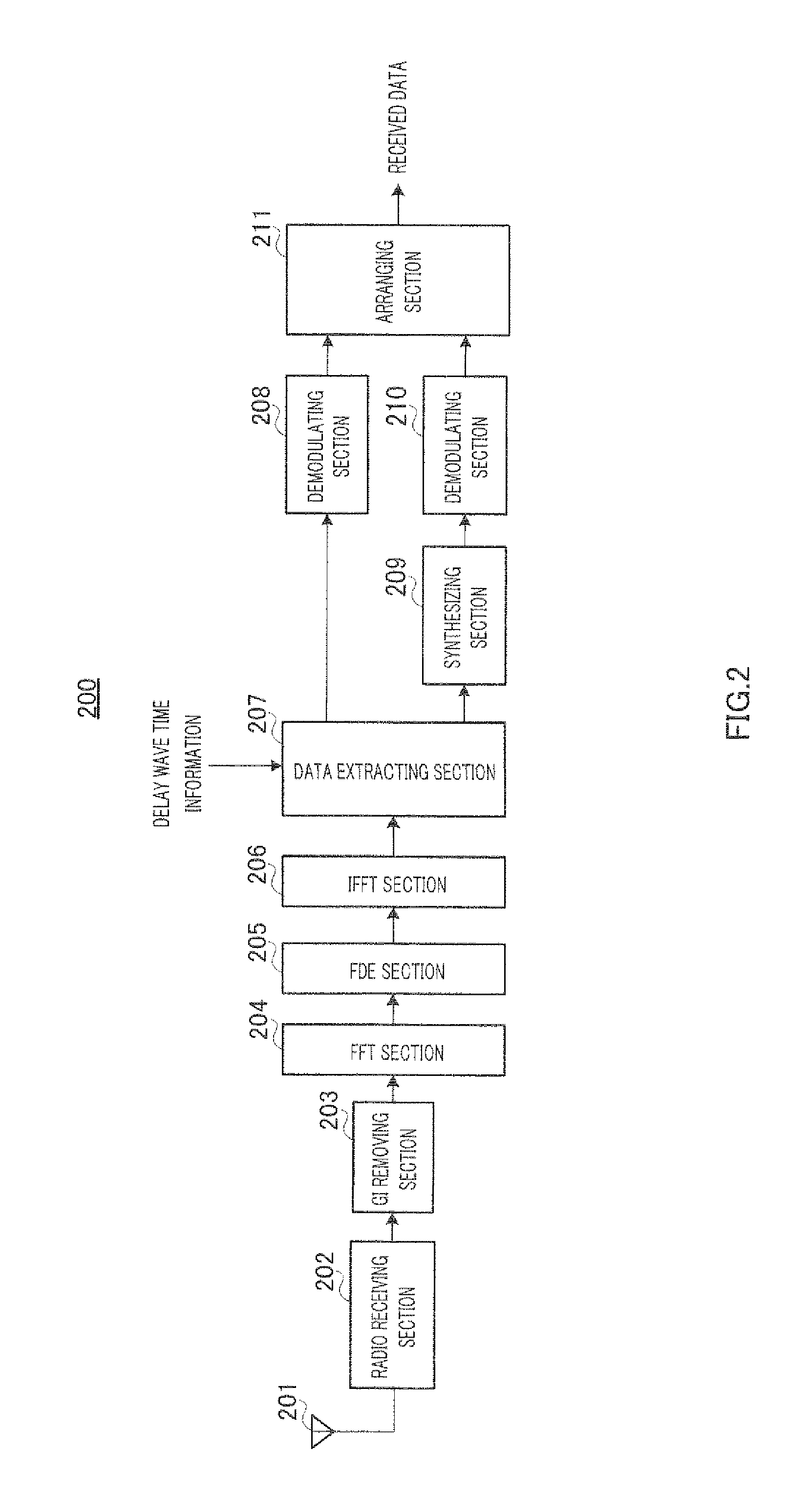
[0019]Hereinafter, the configurations of the radio transmitting apparatus and radio receiving apparatus according to the present embodiment will be explained. FIG. 1 shows the configuration of radio transmitting apparatus 100 according to the present embodiment, and FIG. 2 shows the configuration of radio receiving apparatus 200 according to the present embodiment.

[0020]In radio transmitting apparatus 100 shown in FIG. 1, dividing section 101 receives as input transmission data and delay wave time information from the receiving section (not shown).

[0021]Here, the delay wave time information is fed back from radio receiving apparatus ...


PUM


Abstract

A wireless transmission apparatus in which degradation of error-rate characteristics can be avoided without decreasing a data rate in the mobile communication using a pre-coding together with a FDE. In this apparatus, a modulation unit (102) modulates a first data among transmission data with a first modulation method and generates a first symbol string, a modulation unit (103) modulates a second data among the transmission data with a second modulation method whose modulation multi-level number is larger than that of the first modulation method and generates a second symbol string, and a reproduction unit (104) reproduces the second symbol string and obtains a plurality of second symbol strings. An arrangement unit (105) arranges the plurality of the second symbol strings to both sides of the first symbol string and a pre-coding unit (106) performs a pre-coding to each symbol string after arrangement.

Description

TECHNICAL FIELD[0001]The present invention relates to a radio transmitting apparatus, radio receiving apparatus and block forming method.BACKGROUND ART[0002]To realize data rates over 100 Mbps for the next generation mobile communication system, various studies regarding radio transmission schemes that are suitable for high speed packet transmission are going on. Because it is necessary to widen the bandwidth of the frequency band to be used to perform such high speed packet transmission, studies to use the bandwidth around 100 MHz are going on.[0003]If such wideband transmission is performed in mobile communication, it is known that a communication channel becomes a frequency selective channel formed with a plurality of paths of varying delay times. Therefore, with wideband transmission in mobile communication, preceding symbols interfere with subsequent symbols, causing inter-symbol interference and deteriorating error rate performance. Further, in a frequency selective channel, c...

Claims


Application Information

Patent Timeline
IPC IPC(8): H04L27/00
CPCH04L25/0242H04L25/03159H04L25/03343H04L27/265H04L27/2602H04L27/2627H04L27/0008H04L27/26526
Inventor MIYOSHI, KENICHITAKAOKA, SHINSUKEADACHI, FUMIYUKITOMEBA, HIROMICHITAKEDA, KAZUKI
Owner PANASONIC CORP
Learn More