Determining positional information

a position information and apparatus technology, applied in direction finders using radio waves, using reradiation, radio wave reradiation/reflection, etc., can solve the problems of limiting the system accuracy, the need to precisely synchronise each receiver and the computer, and the failure of the position estimation procedure. to achieve the effect of reducing the data rate of the messag

Active Publication Date: 2010-07-06
CAMBRIDGE CONSULTANTS LTD
View PDF31 Cites 48 Cited by
  • Summary
  • Abstract
  • Description
  • Claims
  • Application Information

AI Technical Summary

Benefits of technology

[0173]By varying a characteristic of the sequence of pulses emitted by the transmitter, it is possible to transmit data between the transmitter and receiver.
[0174]Preferably the rate of varying the characteristic of the pulse sequence is significantly lower than the pulse frequency. In this way, the data rate of the message can be made much lower than the radio-frequency of the system itself.

Problems solved by technology

Problems arise in the prior art system if the direct signal from the object to one of the receivers is weak compared to a delayed reflection of the signal, for example where there is an obstruction between the object and the receiver.
In this case, the delayed signal reflection may be incorrectly identified as the pulse arrival time, which in turn can cause the position estimation procedure to fail dramatically.
Furthermore, whilst each prior art receiver unit is relatively simple, the need to precisely synchronise each receiver and the computer can require accurate and expensive timing circuitry.
Additionally, the reliance on arc-fitting techniques can limit the accuracy of the system and can also introduce ambiguities.
On the other hand, the elements should not be too large, because they may become physically too big for the array, and because grating lobe effects may occur at larger spacings between the elements.
It is also possible to have one or more receiving elements arranged out of a plane in which the others are arranged, but the angular computations can become more complicated and potentially more ambiguous.
Thus signals coinciding with the input sampling clock frequency are reinforced, and other (noise) frequencies tend to cancel out, thereby potentially increasing the signal-to-noise ratio of the system.
Such anomalous objects may be intruders, lacking the necessary transmitting tags, for example.

Method used


Image

  • Determining positional information
  • Determining positional information
  • Determining positional information

Examples


first embodiment

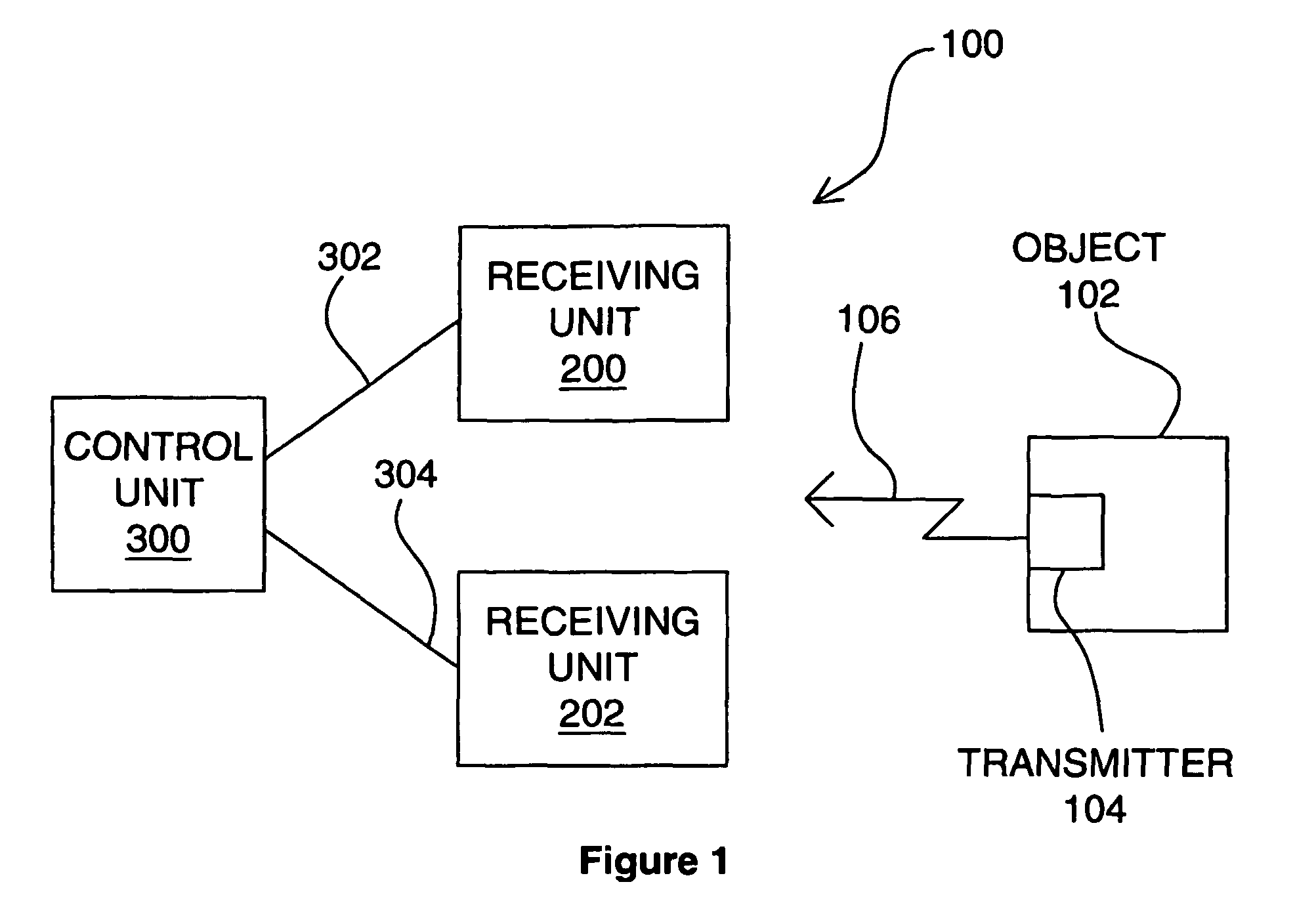
[0246]FIG. 1 is an overview of the positioning system. With reference to FIG. 1, the positioning system 100 comprises an object to be located 102, a transmitter 104 associated with or contained in the object 102 and outputting a signal 106, a pair of receiving apparatuses 200, 202, and a control unit 300. The receiving apparatuses 200, 202 are connected to the control unit 300 by data links 302, 304. As discussed in more detail later variants of the system may be operated in passive mode, in which the transmitter is located remote from the object, and the signals received at the receivers are reflections from the object of transmitted signals.

[0247]The receiving units 200, 202 pass to the control unit 300 via the links 302, 304 data representative of the signal 106 received at the receiving units. The control unit then processes the data received from the receiving units so as to determine the angular position of the object with respect to each receiving unit. The angular position i...

second embodiment

[0254]FIG. 4 is a schematic of the positioning system, in which the receiving units and the control unit are interconnected in an alternative configuration. In FIG. 4, a first receiving unit 200 serves as a communications hub between the further receiving units 202, 204, 206 and the control unit 300. The data links 310, 312, 314 between the first 200 and further receiving units 202, 204, 206 and the data link 302 between the first receiving unit 200 and the control unit 300 may as before be electrical wires, radio links or otherwise.

third embodiment

[0255]FIG. 5 is a schematic of the positioning system. In FIG. 5, a control unit 300 is located within a first receiving unit 200, which receiving unit 200 is connected to the further receiving units 202, 204, 206 via data links 310, 312, 314 as before.

[0256]The operation of the control unit and receiving units will be described further later. First, the active object 102 will be described in more detail, with reference to FIGS. 6 and 7.

Description of the Active Object

[0257]FIG. 6 is an overview of an active object in the positioning system. In FIG. 6, the object 102 comprises a transmitter unit 104 coupled to a signal generation unit 120, which units together produce the signal 106.

[0258]FIG. 7 is a schematic showing the object of FIG. 6 in more detail. With reference to FIG. 7, the transmitter unit (or ‘tag’) 104 comprises a single antenna 118, and the signal generation unit 120 comprises a crystal oscillator 122, phase-locked loop (PLL) circuitry 124, a pulse repetition frequency...


PUM


Abstract

Apparatus for determining positional information relating to an object, comprising: means for receiving, comprising a plurality of receiving elements; detection means for detecting signals received at the receiving elements and for generating output signals representative of the received signals; and processing means operable to apply, for each receiving element, a process to the output signal generated from the signal received at that receiving element separately from any output signal generated from a signal received at any other receiving element, so as to obtain a respective value of a parameter representative of the signal received at that receiving element, the processing means being further operable to compare the values of the parameter thus obtained so as to, obtain positional information relating to the object.

Description

[0001]This application is the US national phase of international application PCT / GB2004 / 004648, filed 3 Nov. 2004, which designated the U.S. and claims priority of GB 0325622.9, filed 3 Nov. 2003, the entire contents of each of which are hereby incorporated by reference.BACKGROUND AND SUMMARY[0002]The invention relates to apparatus for determining positional information relating to an object incorporating a transmitter, apparatus for searching a detection volume for radiating objects, a system for locating an object, and in particular to an object incorporating a transmitter for use with an object in an object positioning system, a method of determining positional information, a computer readable medium, a computer program product, and a signal.[0003]The invention finds particular application in the fields of object tracking systems, intrusion detector systems, inventory control, vehicle collision detection and security and workforce tracking systems.[0004]A known prior art system f...

Claims


Application Information

Patent Timeline
Patent Type & Authority Patents(United States)
IPC IPC(8): G01S13/42G01S5/04G01S13/02G01S13/87
CPCG01S5/04G01S13/0209G01S13/878G01S13/888G01S13/931G01S13/765G01S2013/9329
Inventor OSWALD, GORDON KENNETH ANDREWGEOGHEGAN, ALEXANDRA JOANNABELL, CHARLES PETERRUSS, NICHOLAS SIMONDEL MISTRO, MARIOBURCHETT, MICHAEL HUGHPHILLIPS, DESMOND KEITHUTSI, VINCENT ARNE
Owner CAMBRIDGE CONSULTANTS LTD
Why Eureka
Try Eureka