Integrated service tube and impingement baffle for a gas turbine engine

a gas turbine engine and integrated technology, applied in the direction of machines/engines, liquid fuel engines, lighting and heating apparatus, etc., can solve the problem of unusable oil coking in the service tub

Active Publication Date: 2010-06-03
GENERAL ELECTRIC CO
View PDF29 Cites 74 Cited by
  • Summary
  • Abstract
  • Description
  • Claims
  • Application Information

AI Technical Summary

Problems solved by technology

High temperature operation tends to cause undesirable oil coking within the service tubes.

Method used


Image

  • Integrated service tube and impingement baffle for a gas turbine engine
  • Integrated service tube and impingement baffle for a gas turbine engine
  • Integrated service tube and impingement baffle for a gas turbine engine

Examples


Embodiment Construction

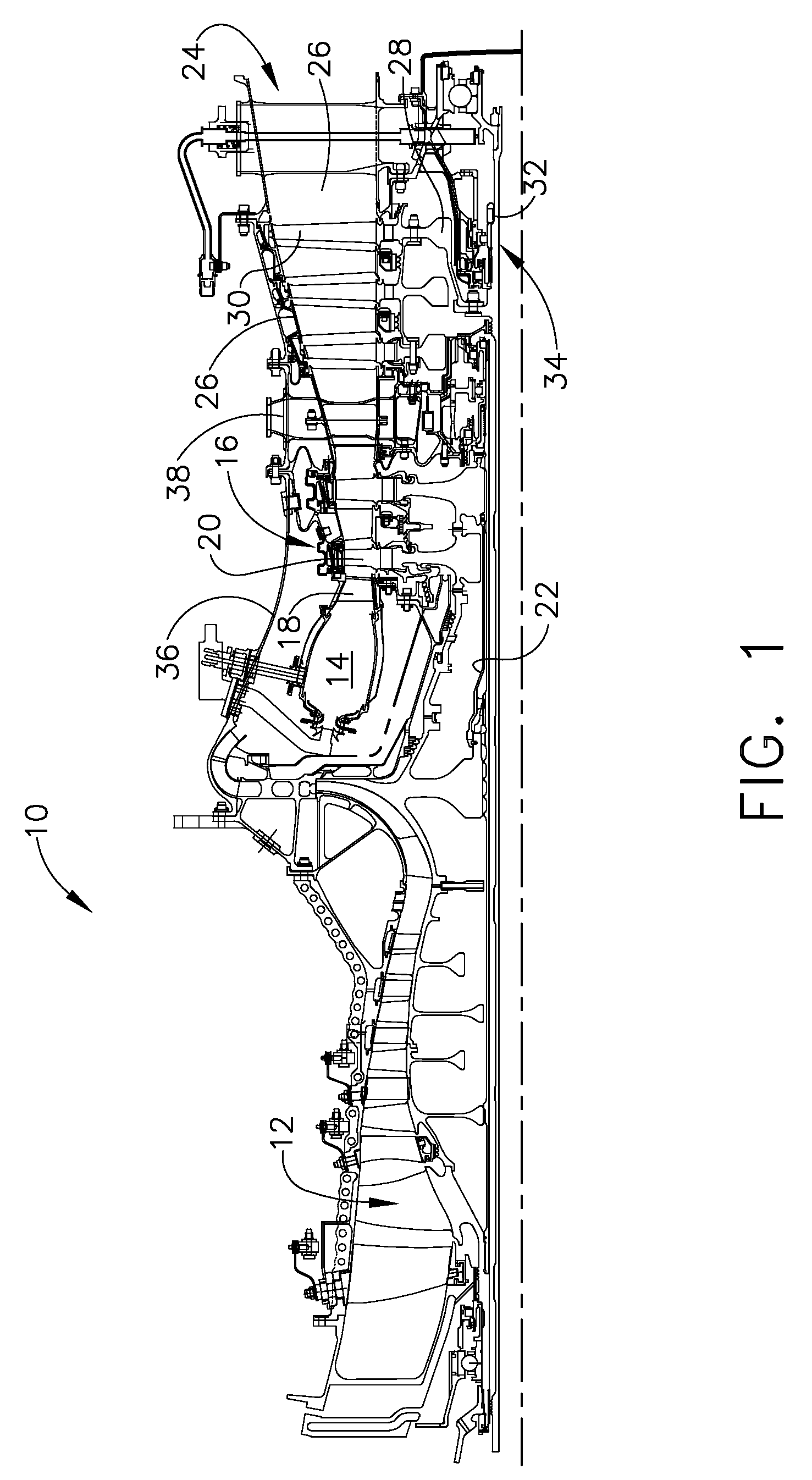
[0016]Referring to the drawings wherein identical reference numerals denote the same elements throughout the various views, FIGS. 1 and 2 depict a portion of a gas turbine engine 10 having, among other structures, a compressor 12, a combustor 14, and a gas generator turbine 16. In the illustrated example, the engine is a turboshaft engine. However, the principles described herein are equally applicable to turboprop, turbojet, and turbofan engines, as well as turbine engines used for other vehicles or in stationary applications.

[0017]The compressor 12 provides compressed air that passes into the combustor 14 where fuel is introduced and burned to generate hot combustion gases. The combustion gases are discharged to the gas generator turbine 16 which comprises alternating rows of stationary vanes or nozzles 18 and rotating blades or buckets 20. The combustion gases are expanded therein and energy is extracted to drive the compressor 12 through an outer shaft 22.

[0018]A work turbine 24...


PUM


Abstract

A service tube apparatus for a gas turbine engine includes a service tube assembly having: (a) an elongated, hollow service tube; and (b) a service tube baffle surrounding the service tube which is pierced with a plurality of impingement cooling holes.

Description

BACKGROUND OF THE INVENTION[0001]This invention relates generally to gas turbine engine turbines and more particularly to structural members of such engines.[0002]Gas turbine engines frequently include a stationary turbine frame (also referred to as an inter-turbine frame or turbine center frame) which provides a structural load path from bearings which support the rotating shafts of the engine to an outer casing, which forms a backbone structure of the engine. Turbine frames commonly include an annular, centrally-located hub surrounded by an annular outer ring, which are interconnected by a plurality of radially-extending struts, as well as one or more service tubes which carry fluids to and from the hub. The turbine frame crosses the combustion gas flowpath of the turbine and is thus exposed to high temperatures in operation.[0003]From a thermodynamic standpoint it is desirable to increase operating temperatures within gas turbine engines as much as possible to increase both outpu...

Claims


Application Information

Patent Timeline
Patent Type & Authority Applications(United States)
IPC IPC(8): F01D25/00
CPCF01D9/065F05D2260/201F01D25/18
Inventor MANTEIGA, JOHN ALANPARKS, ROBERT JOHN
Owner GENERAL ELECTRIC CO
Why Eureka
Try Eureka