Screw compressor

a screw compressor and compressor technology, applied in the direction of positive displacement liquid engine, piston pump, liquid fuel engine, etc., can solve the problems of vibration noise, affecting the efficiency of the compressor of this kind, and producing a high frequency noise of several thousand hertz, so as to reduce the noise of the screw compressor, reduce the installation area, and compact the compressor

Active Publication Date: 2010-06-03
HITACHI IND EQUIP SYST CO LTD
View PDF2 Cites 27 Cited by
  • Summary
  • Abstract
  • Description
  • Claims
  • Application Information

AI Technical Summary

Benefits of technology

[0010]The present invention is made in view of the above problems, and is directed, in particular, to a screw compressor having an air-cooled heat exchanger, which is a component having the largest sound emitting area in the compressor unit. The object of the present invention is to provide a compact screw compressor emitting less noise and using a small installation area without disturbing the cooling capability of a heat exchanger by providing the air-cooled heat exchanger at a central part in the unit.
[0011]In order to achieve the above object, according to the present invention, there is provided an oil free screw compressor comprising: a compressor body having a pair of male and female screw rotors; an air-cooled heat exchanger for cooling a lubricating oil in the compressor; an air-cooled heat exchanger for cooling a compressed air discharged from the compressor; and a case for receiving the above components, wherein the oil free screw compressor further comprises: a motor disposed at the bottom of the case for driving the compressor; and a duct which takes in air from an area below the case and discharges it from a ceiling portion and whose central part extends above the motor; wherein the above air-cooled heat exchanger is provided in an inclined manner at a central part of the duct; and wherein a suction duct for reducing noise of the air-cooled heat exchanger is provided closer to a suction side than to the central part of the duct.
[0022]According to the present invention, while reducing the noise of the screw compressor, the installation area can be reduced and the compressor can be made compact.

Problems solved by technology

Therefore, leakage through a clearance between rotors and leakage through a clearance formed in the teeth groove, or in the periphery of a compressor chamber greatly affect the efficiency of the compressor of this kind.
The pressure pulsation during the discharge is transmitted from the compressor body itself or the pipes connected to the compressor body to a cooler (heat exchanger) for air cooling of the compressor, causing vibration noise.
In particular, as compared to an oil injection screw compressor whose rotors rotate at 3000 to 4000 rpm, the rotors of the oil free screw compressor rotate at a very high speed, producing a high frequency noise of several thousand hertz.
According to Patent Document 1, since a cooler is provided close to a delivery port of a cooling wind of the case, vibration noise of the heat exchanger is liable to directly leak to outside of the case.
Therefore, the vibration noise of the heat exchanger may go forward along the duct to leak to outside of the case.

Method used


Image

  • Screw compressor
  • Screw compressor
  • Screw compressor

Examples


Embodiment Construction

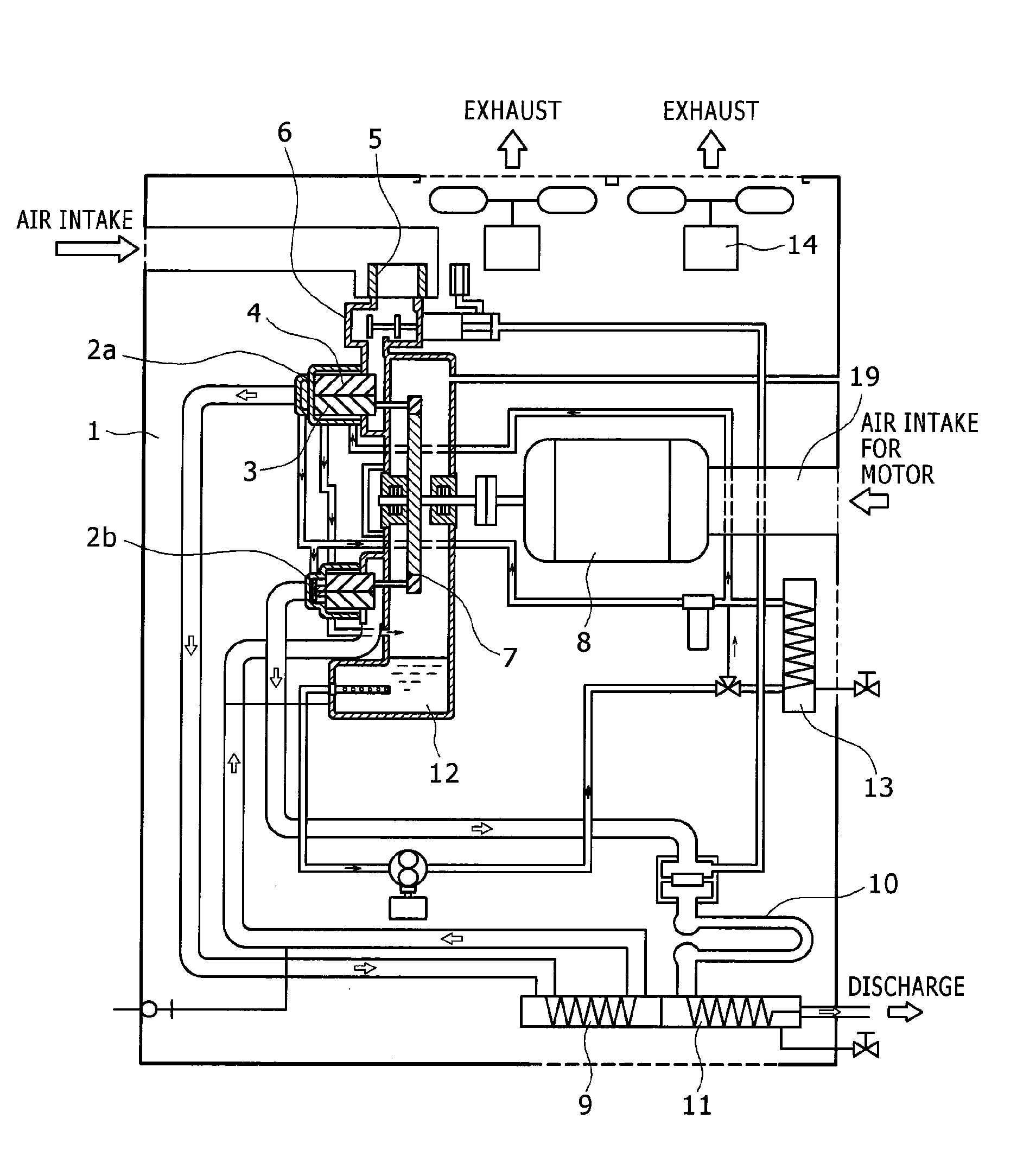
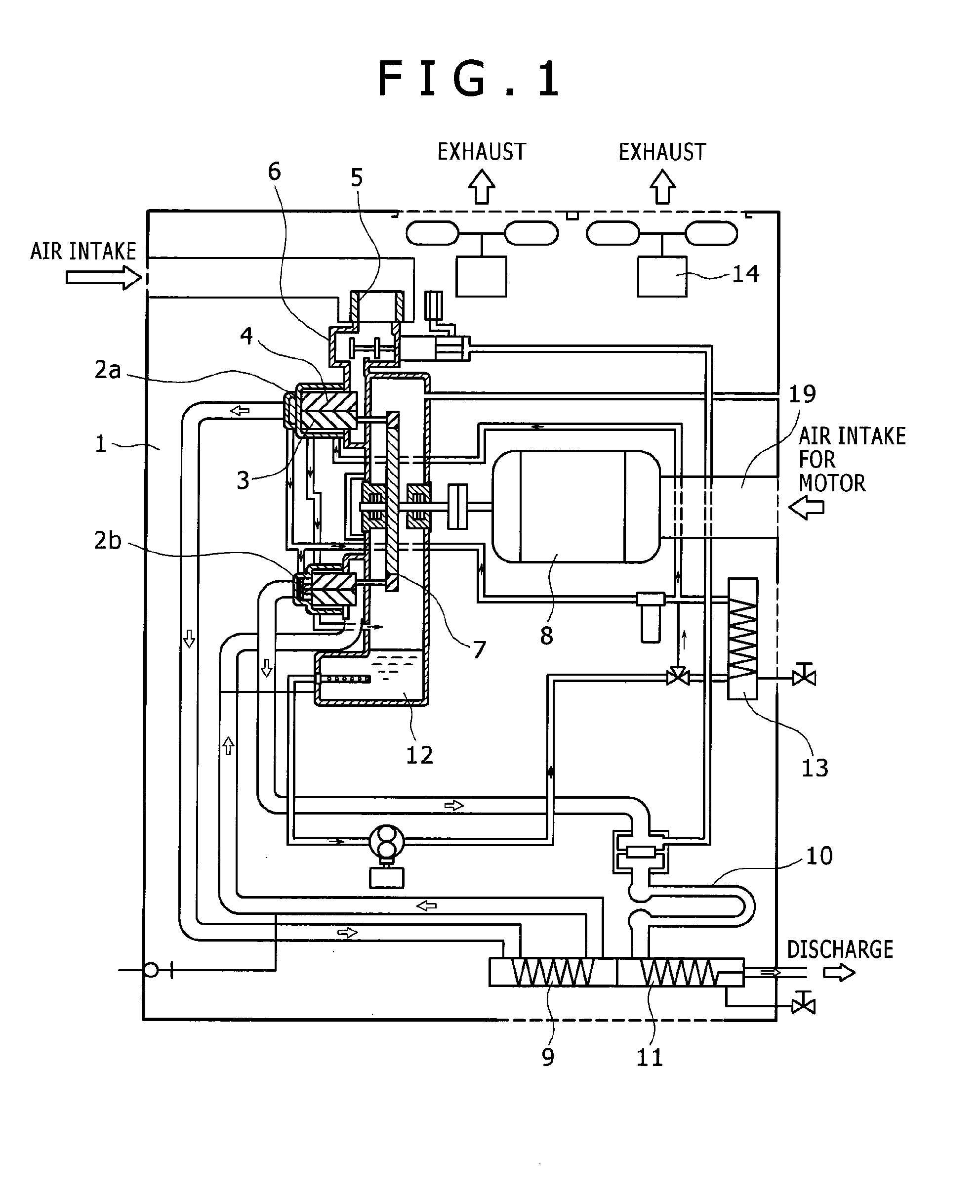
[0026]The present invention is generally directed to a screw compressor having an air-cooled heat exchanger and is not limited to an oil free screw compressor. However, as compared to an oil injected screw compressor, it is preferable to be used in the oil free type. Therefore, hereinafter, as an embodiment of the present invention, there is described an oil free screw compressor having a compressor body including a pair of male and female screw rotors which can rotate in a non-contact state with no oil supplied.

[0027]FIG. 1 shows an overall structure of the oil free screw compressor and a flow of a compressed air and lubricating oil. In FIG. 1, the oil free screw compressor received in the compressor unit case 1 is a two-stage compressor and has a low-pressure stage compressor body 2a and a high-pressure stage compressor body 2b. A throttle valve 6 is provided on an upstream side of a suction gas passage of the low-pressure stage compressor body 2a. Further, the compressor body rec...


PUM


Abstract

A screw compressor comprising: a pair of male and female screw rotors; and an air-cooled heat exchanger, wherein the air-cooled heat exchanger is provided above a motor for driving the compressor body; wherein, with respect to a cooling wind for the air-cooled heat exchanger, the air-cooled heat exchanger is inclined to the upstream side; wherein the uppermost portion of a unit suction port for the air-cooled heat exchanger cooling winds is positioned below the uppermost portion of the air-cooled heat exchanger positioned at the uppermost portion; wherein the lowermost portion of the unit suction port for the air-cooled heat exchanger cooling wind is positioned below the lowermost portion of the air-cooled heat exchanger positioned at the lowermost portion; and wherein the cooling wind for the air-cooled heat exchanger is exhausted from a ceiling portion of the compressor unit. With this structure, it becomes possible to provide a compact screw compressor with less noise whose installation area can be reduced.

Description

BACKGROUND OF THE INVENTION[0001]1. Field of the Invention[0002]The present invention relates to a screw compressor. More specifically, it relates to a screw compressor capable of reducing noise caused by operation of the compressor.[0003]2. Description of the Related Art[0004]There is known an oil free, or no-oil injected screw compressor which compresses air by using its pair of male and female screw rotors capable of rotating in a non-contact state with no oil supplied. The oil free screw compressor has a compressor body to compress air. The temperature of the compressed air discharged from the compressor body is very high. Therefore, in most cases, a cooler (heat exchanger) for cooling the compressed air is installed. The compressed air discharged from the compressor body passes through connection pipes inside the cooler and compressor unit to be discharged to outside of the compressor unit. As conventional technologies of this kind, Patent Document 1 discloses a structure of a ...

Claims


Application Information

Patent Timeline
Patent Type & Authority Applications(United States)
IPC IPC(8): F01C1/16F04B17/00
CPCF04B39/0033F04C18/16F04C23/00F04C29/06F04C29/04F04C29/045F04C23/001
Inventor FUJIMOTO, HIDEKINISHIMURA, HITOSHINAGAI, YUSUKE
Owner HITACHI IND EQUIP SYST CO LTD
Why Eureka
Try Eureka