
Eureka
For R&D, Eureka makes reading and utilizing patents & technical documents easy.
Eureka AIR
Designed for self-driven R&D workflows. Generate viable solutions, solve complex R&D challenges, empower your innovation with AI.

Eureka Materials
Designed for material experts only. Revolutionize your material R&D, from search, analyze, to developing new materials.

TechResearch
Generate reliable direction feasibility study reports for your R&D in just a few steps.

TechSeek
Discover and master advanced knowledge NOW. Basics, ideas, possibilities, all at once.

TechMind
As an expert in R&D Theories, TechMind can generates customized viable solutions instantly.

TechRisk
Analyze your overall solution with one click, know your potential R&D risks in advance.

TechMonitor
Get weekly tech updates, stay abreast of the latest tech innovations and key insights.
Desulfurizer, hydrogen generation apparatus, fuel cell power generating system, and desulfurizing agent cartridge
- Summary
- Abstract
- Description
- Claims
- Application Information
AI Technical Summary
Benefits of technology
Problems solved by technology
Method used
Image

Examples
embodiment 1
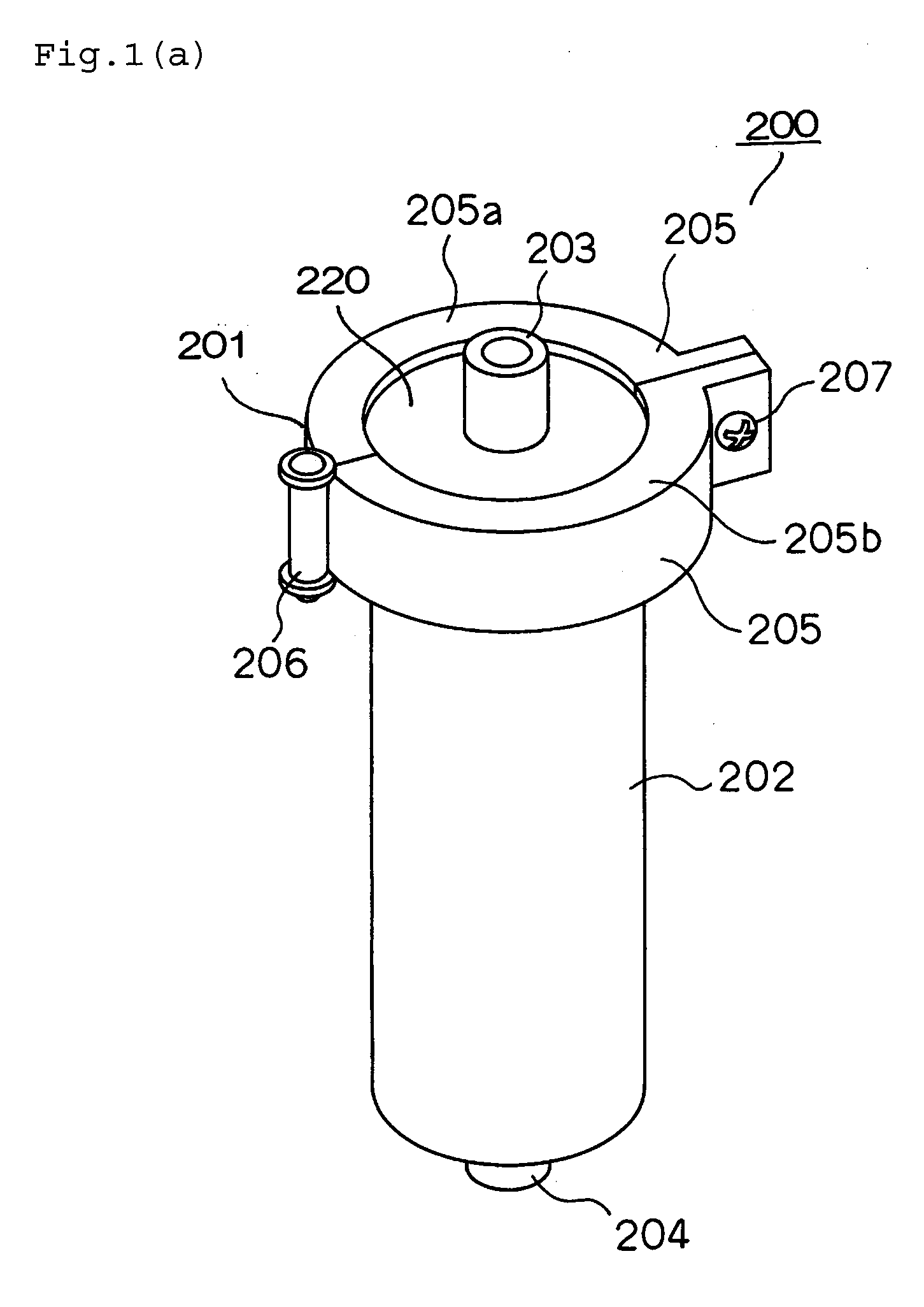
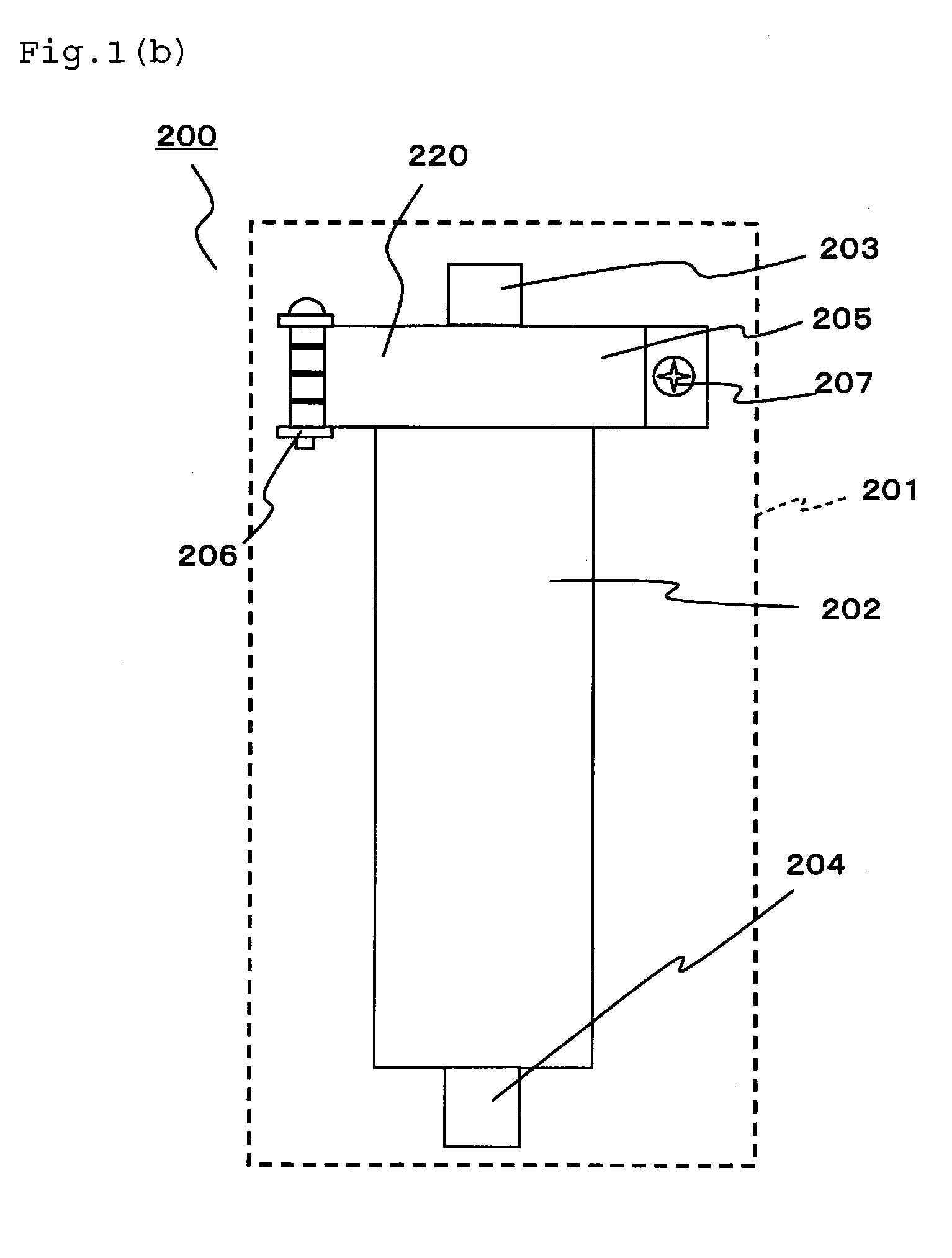
[0138]FIG. 1(a) is a perspective outside drawing of a desulfurizer 200 of embodiment 1 according to the present disclosure. FIG. 1(b) is a front view of the desulfurizer 200 of embodiment 1 according to the present disclosure. The desulfurizer 200 of embodiment 1 has an outer container 201 made of metal on an outer side thereof. The outer container 201 includes a cylindrical outer-container body 202, a cover portion 220 provided on an upper part of the outer-container body 202, and a clamp 205 for fixing the outer-container body 202 to the cover portion 220.
[0139]An outer-container inlet 203 being an inlet of material is provided in the cover portion 220, and an outer-container outlet 204 being an outlet of the material is provided in a lower part of the outer-container body 202. The cover portion 220 is configured such that it may be opened from the outer-container body 202 by detaching the clamp 205.
[0140]The clamp 205 is configured in such a manner that two half members 205a and ...
embodiment 2
[0179]Next, a desulfurizer of embodiment 2 according to the present disclosure is described.
[0180]The desulfurizer of embodiment 2 is the same in basic configuration as the desulfurizer of embodiment 1, but different in the configuration of a seal member. Therefore, the following discussion will focus on the differences. The same components as in embodiment 1 are marked with the same reference numerals.
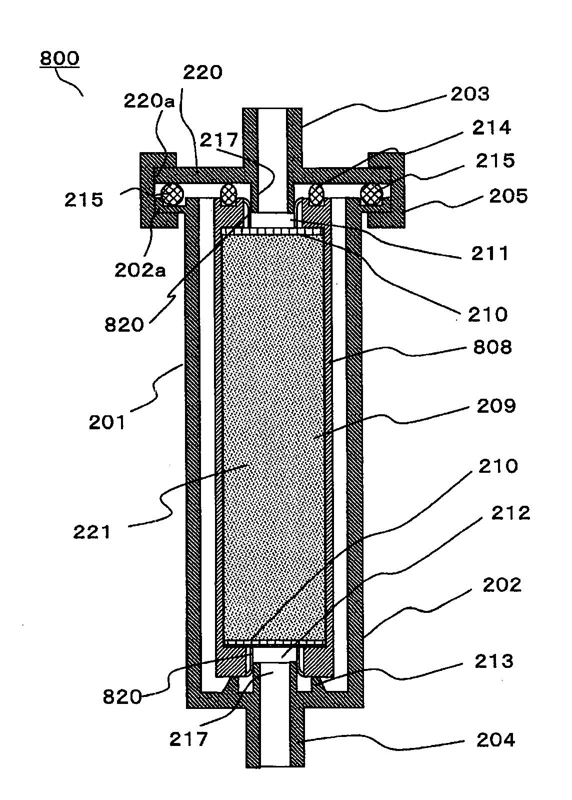
[0181]FIG. 9(a) is a sectional configuration diagram of a desulfurizer 800 of embodiment 2 according to the present disclosure. FIG. 9(b) is an enlarged, sectional configuration diagram of a portion near an inner-container inlet 211 in FIG. 9(a). FIG. 10(a) is a plan view of a seal member in embodiment 2. FIG. 10(b) is a section view along AA′ of FIG. 10(a).
[0182]A seal member 818, which corresponds to an example of a partition portion of the present disclosure, is configured such that incisions 819 are formed in the seal member 818 so that the seal member is easily broken unlike the ...
embodiment 3
[0192]Next, a desulfurizer 300 of embodiment 3 according to the present disclosure is described. The desulfurizer 300 of embodiment 3 is the same in basic configuration as that of embodiment 1, but different in configuration of each of an inner-container outlet and an outer-container outlet. Therefore, the following discussion will focus on the differences from embodiment 1. The same components as in embodiment 1 are marked with the same reference numerals.
[0193]FIG. 13 is a relevant-part section view of the desulfurizer 300 of embodiment 3 of the present disclosure. In the desulfurizer 300 of embodiment 3, an outer-container outlet 304 of an outer container 301 is provided in a side face of an outer-container body 302 unlike in embodiment 1. In addition, a plurality of L-shaped projecting portions 317 are provided from a lower inner-wall of the outer-container body 302 in place of the projecting portion 217 in the outer-container outlet 204 in embodiment 1.
[0194]FIG. 14(a) is a fro...
PUM
| Property | Measurement | Unit |
|---|---|---|
| Force | aaaaa | aaaaa |
| Shape | aaaaa | aaaaa |
| Transparency | aaaaa | aaaaa |
Abstract
Description
Claims
Application Information
 - R&D Engineer
- R&D Manager
- IP Professional
- Industry Leading Data Capabilities
- Powerful AI technology
- Patent DNA Extraction
Browse by: Latest US Patents, China's latest patents, Technical Efficacy Thesaurus, Application Domain, Technology Topic, Popular Technical Reports.
© 2024 PatSnap. All rights reserved.Legal|Privacy policy|Modern Slavery Act Transparency Statement|Sitemap|About US| Contact US: help@patsnap.com