Micro-Valve

a micro-valve and valve body technology, applied in the direction of diaphragm valves, catheters, engine diaphragms, etc., can solve the problems of uncontrollable flow of therapeutic products, complex insulin release pattern of people without diabetes, and easy influence of the pressure at the outlet of the pumping chamber, so as to reduce the overall volume of the pump, prevent uncontrollable flow, and reduce the activation pressure

Inactive Publication Date: 2010-06-03
INSULET NETHERLANDS BV
View PDF11 Cites 54 Cited by
  • Summary
  • Abstract
  • Description
  • Claims
  • Application Information

AI Technical Summary

Benefits of technology

[0013]The present invention is advantageous in providing a one-way valve having an accurately defined activation pressure. By forming the outer portion of the membrane stiffer than the inner portion such that the membrane deflection is substantially restricted to only the inner portion, it becomes possible to align, during manufacture, the outer portion of the membrane with respect to the valve seat. Also, the deflectable portion of the membrane can be restricted to only that portion immediately adjacent the valve seat. In these ways, an accurately defined and consistent activation pressure across a batch of valves may be provided.
[0025]Preferably, the inlet valve has a lower activation pressure than the outlet valve to prevent uncontrolled flow of therapeutic product through the pump. The difference in activation pressure between the inlet valve and the outlet valve may be effected by providing similar inlet and outlet valves, wherein a height of the valve seat of the outlet valve is greater than a height of the valve seat of the inlet valve. In other words, the valve seat of the inlet valve extends beyond the plane of the outer membrane portion of the inlet valve towards the inner membrane portion to a lesser extent than does the valve seat of the outlet valve.

Problems solved by technology

The pattern of insulin release in people without diabetes is complex.
The system described in U.S. Pat. No. 4,486,190 suffers a drawback in that the filling efficiency of the pumping chamber is affected by the pressure at the outlet.
In addition, the design of the system is prone to allowing uncontrolled flow of therapeutic product due to leaking of the inlet valve.
To prevent this, the activation pressure of the inlet valve could be increased but this would then compromise the pumping efficiency.
The need to glue the membrane during the assembly process significantly increases the complexity of the manufacture of the micro-pump.
It also serves to increase the opportunity for assembly problems and seepage of the glue.
These problems are significantly increased when an attempt is made to reduce the size of micro-pumps yet further.
The provision of a one-way check-valve at the outlet of the pumping chamber having a sufficiently high activation pressure to prevent free flow of liquid under expected operating conditions is necessary for micro-pumps for use in infusion systems, where uncontrolled flow of therapeutic product into the patient would be unacceptable.
In addition, the devices described are not suitable for disposable, short term use.
However, the membrane material is inherently flexible giving rise to misalignment of the inlet, outlet and valve seat during manufacture.
This can adversely affect control of the activation pressure.
It is also observed in this type of valve design that the tension of the valve membrane cannot be accurately controlled during the assembly of the device and that this leads to variability in the performance of the valve.

Method used


Image

  • Micro-Valve
  • Micro-Valve
  • Micro-Valve

Examples


Embodiment Construction

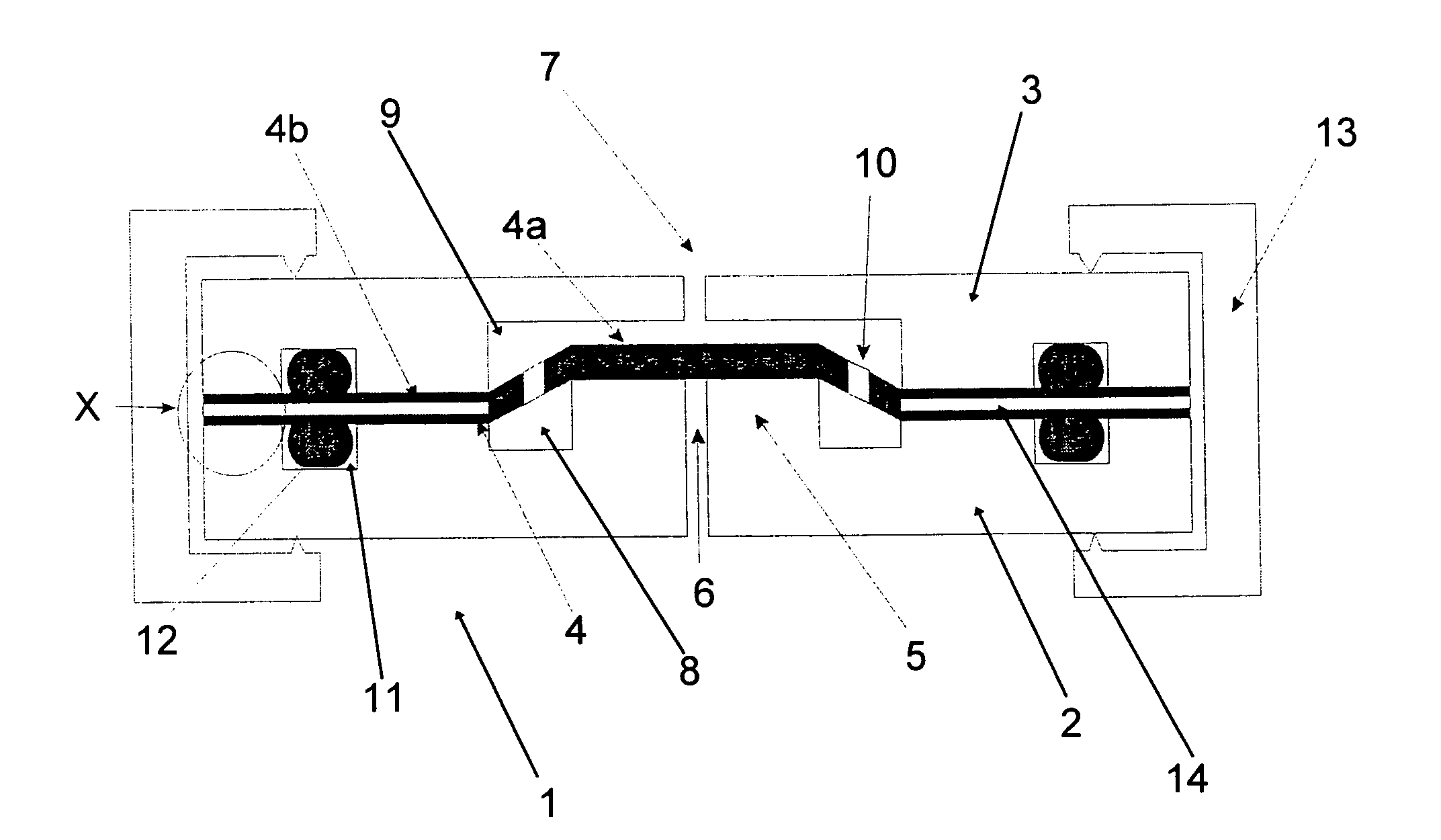
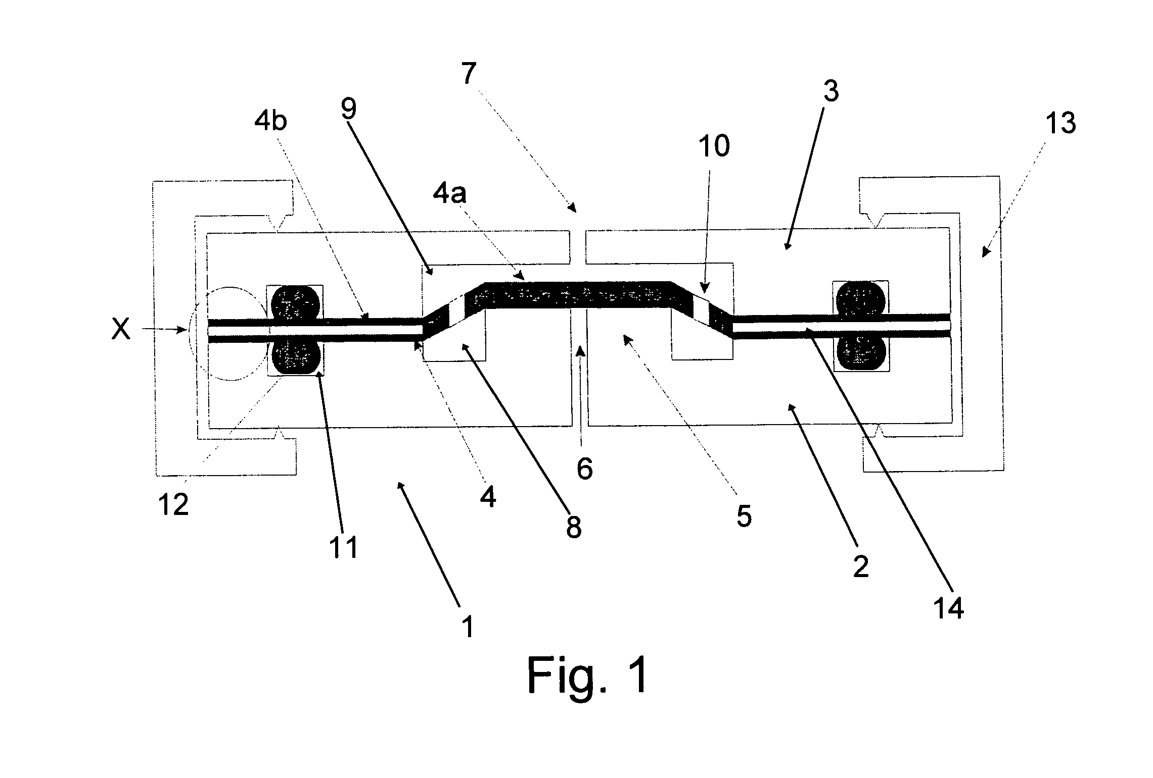
[0033]Turning firstly to FIG. 1 there is shown the first embodiment of the valve in accordance with the present invention. The valve 1 comprises a first body portion 2, a second body portion 3 and a membrane 4 trapped between the first and second body portions 2,3. The membrane 4 comprises an inner portion 4a and an outer portion 4b. The valve 1 is essentially rectangular. However, it will be understood that other shapes may be suitable such as cylindrical, hexagonal, octagonal, or square. The first body portion 2 has a raised valve seat 5 that extends beyond a plane of the outer membrane portion 4b such that the inner membrane portion 4a is stretched over the valve seat 5. The inner membrane portion 4a and at least a portion of the outer membrane portion 4b are formed of elastomeric rubber material.

[0034]A valve inlet 6 is formed in the valve seat 5 and a valve outlet 7 is disposed opposite the inlet 6 on the other side of the membrane 4 from the inlet 6. Cavities 8 and 9 are forme...


PUM


Abstract

A one-way valve comprises a seat and a membrane having an inner portion that is stretched over the seat, wherein, in use, the inner membrane portion is selectively deflected from the seat such that a fluid path is created from one side of the membrane to the other so as to open the valve, and wherein an outer peripheral portion of the membrane is stiffer than the inner portion such that the membrane deflection is substantially restricted to only the inner portion. The one-way valve may be used in a pump for an infusion system.

Description

FIELD OF THE INVENTION[0001]In devices for the programmed delivery of therapeutic products into the human or animal body, there is generally provided a pressurised reservoir of therapeutic product working in cooperation with a pumping chamber and valve means. The therapeutic product is typically pumped by the device through a tube to a cannula that pierces the patient's skin. The device can be capable of providing a variable rate of infusion of the therapeutic product to the patient over several days. This invention is directed to an improved micro-valve for the pumping chamber.BACKGROUND TO THE INVENTION[0002]Therapeutic products can be administered to a human or animal in a variety of ways and the administration method is often matched to the specific requirements of the therapeutic product and its intended action. While oral administration is typically preferred, some therapeutic products, such as insulin, have to be administered in such as way as to avoid the digestive system, o...

Claims


Application Information

Patent Timeline
Patent Type & Authority Applications(United States)
IPC IPC(8): A61M1/00A61M37/00
CPCA61M2039/246F16K2099/0086A61M2039/2433A61M2205/0244A61M39/24A61M2205/0294F16K99/0015F16K2099/0094F16K99/0001Y10T137/7837F16K7/17F16K15/14
Inventor CEFAI, JOSEPH JOHNSHAPLEY, JULIAN LLEWELLYN
Owner INSULET NETHERLANDS BV
Why Eureka
Try Eureka