Modular control system

a control system and module technology, applied in the field of suspension systems, can solve the problems of incompatibility of the pressurized bellows of known systems with the concentric mounting of the shock absorber, the characteristic change of the coil spring, and the inability to twis

Active Publication Date: 2010-06-03
AIR ELEVATOR
View PDF9 Cites 25 Cited by
  • Summary
  • Abstract
  • Description
  • Claims
  • Application Information

AI Technical Summary

Benefits of technology

[0030]The fixing plate is provided with stud bolts, extending through through holes of the chassis of the vehicle. The stud bolts are threadably engaged with nuts, thus mounting the upper mount unit to the chassis. The outwardly threaded portion of the retractable rod extends through a washer and the annular member of the upper mount unit. This threaded portion has a portion protruding from the second end member, to which a nut is threadably engaged, thus mounting the shock absorber to the upper mount unit. Between the annular concave portion and the receiving plate is a bearing, which allows the adapter to be rotatably supported on the upper mount unit.
[0031]With respect to assembly, the spring receiving members first welded onto the body of the shock absorber. The liquid silicone is then poured into the reservoir defined by the annular inclined surface. The first end member positioned on the lower upper end of the bellows body is then mounted to the spring receiving member by allowing the shock absorber body to extend through the through hole of the first end member. Bolts are threadably engaged with the inwardly threaded portions of the first end member through the concave portions. The tightening force of the bolts will squeeze the O-ring pair, thereby achieving a hermetic sealing of the lower open end of the bellows body.

Problems solved by technology

Problems can be encountered with front suspension struts mounted to the front steerable wheels.
The twisting will undesirably change the characteristics of the coil spring.
Oishi explains that the pressurized bellows of known systems are incompatible with the concentric mounting of shock absorbers.
Oishi states that a disadvantage associated with low-rider actuators known in the prior art is that they produce a particularly harsh ride, with substantially no spring action, because only about half of the original spring is utilized.

Method used


Image

  • Modular control system
  • Modular control system
  • Modular control system

Examples


Embodiment Construction

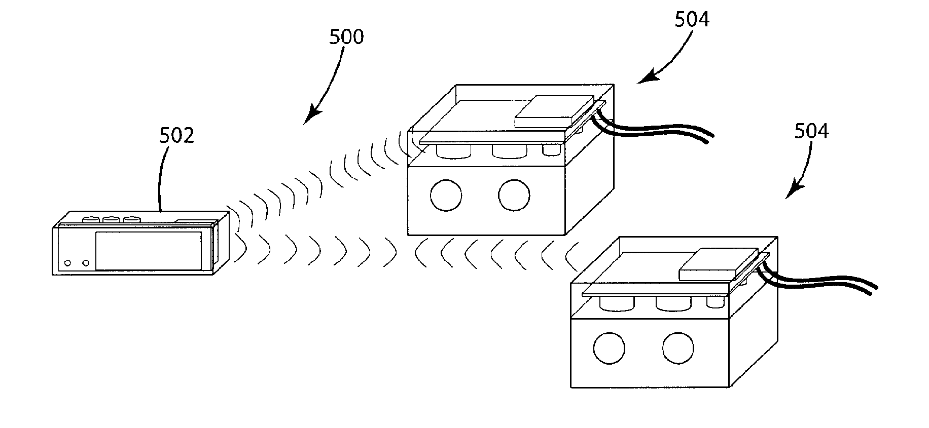
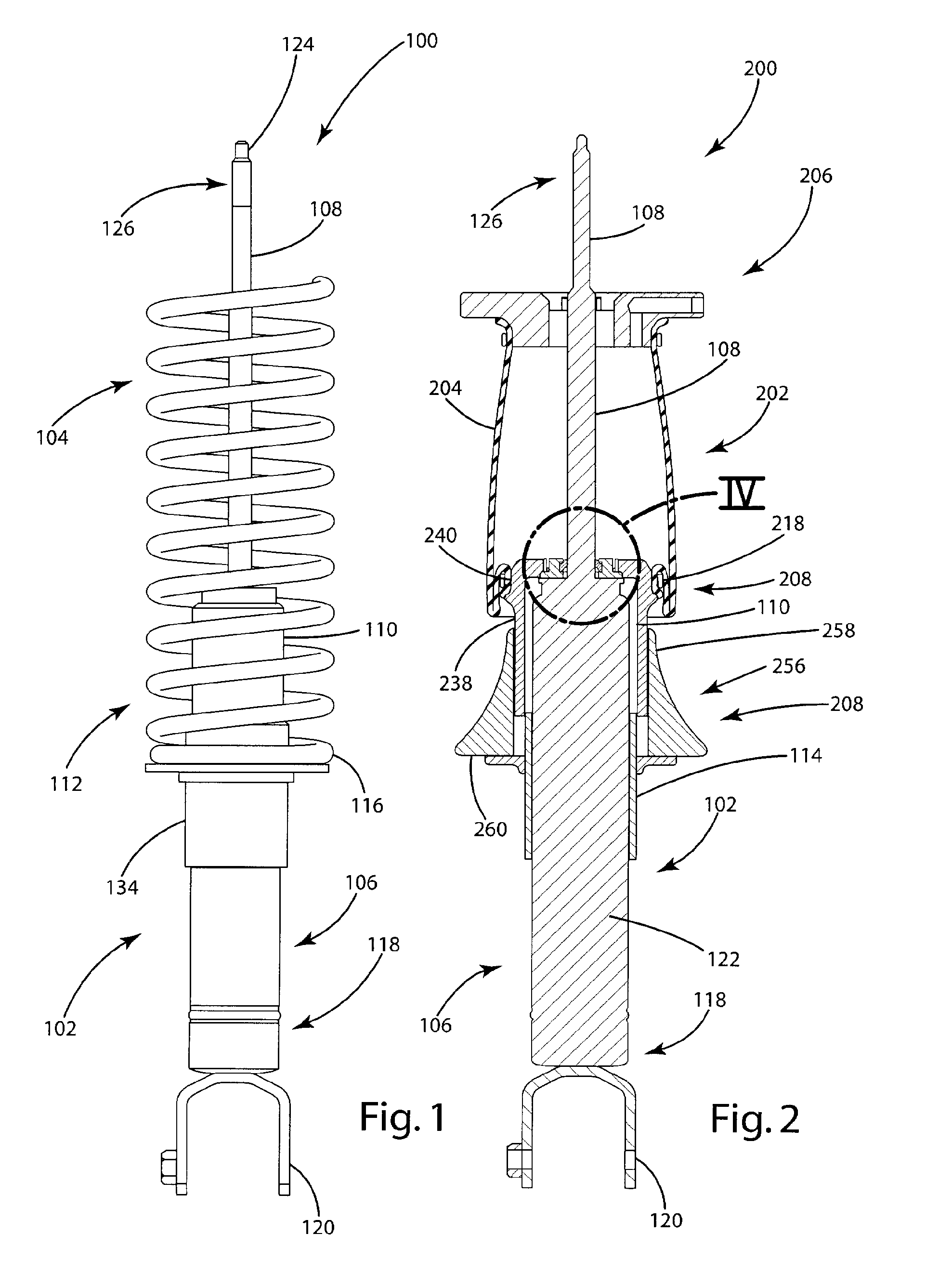
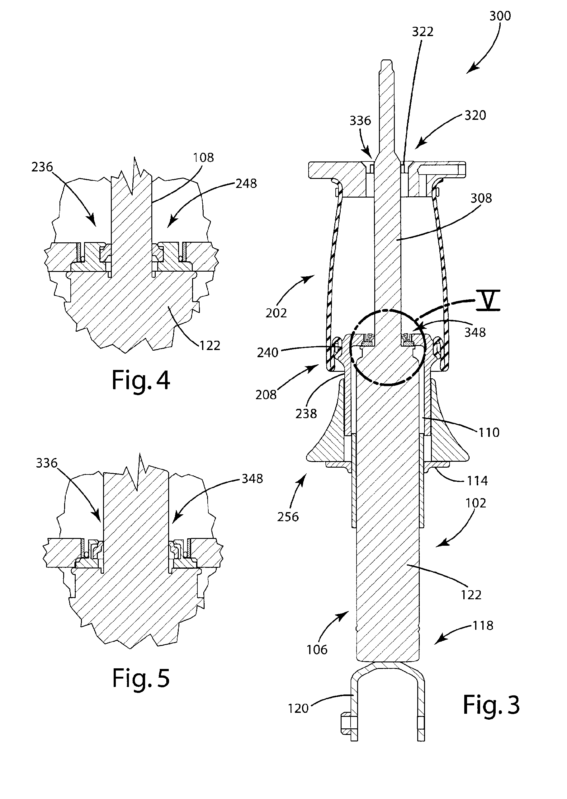
[0085]The principles of the invention are disclosed, by way of example, in modular control systems comprising wireless and wired configurations, as illustrated in FIGS. 16-33. For purposes of background description, a coil-over shock absorber system 100 and air-over shock absorber systems 200, 300 and 400 will first be disclosed herein, and are illustrated in FIGS. 1-15. Following this description, control systems in accordance with the invention will be described, with reference to the illustrations of FIGS. 16-29. As will be made apparent from the description in subsequent paragraphs herein, certain shock absorber systems facilitate the replacement of a coil spring with an air spring (meaning a spring which may be filled with either gaseous or fluid materials), and sealing the internal chambers of the air spring only on the piston of the shock absorber. Further, for facilitating inventory flexibility and variations in piston rod diameters, shock absorber systems may include modula...


PUM


Abstract

A modular control system (500, 510) is disclosed for providing for modular control functions within vehicles. One embodiment of the modular control system (500) includes a driver interface unit (502) for controlling one or more air control units (504) through wireless communications. The air control units (504) can control functions such as air spring pressure, air spring height and the like. Another embodiment of the modular control system (510) uses a driver interface unit (512) for controlling air control units (518) through wire applications (514, 516).

Description

CROSS-REFERENCE TO RELATED APPLICATIONS[0001]This application is based on and claims priority of U.S. Provisional Patent Application Ser. No. 60 / 855,274 filed Oct. 30, 2006.STATEMENT REGARDING FEDERALLY SPONSORED RESEARCH OR DEVELOPMENT[0002]Not applicable.REFERENCE TO A MICROFISHE APPENDIX[0003]Not applicable.BACKGROUND OF THE INVENTION[0004]1. Field of the Invention[0005]The invention relates to suspension systems and, more particularly, relates to a modular control system designed for the vehicle aftermarket that allows wired or wireless communication with multiple electronically controlled services, including air suspensions, adjustable dampers, engine controllers and the like.[0006]2. Background Art[0007]The invention for which an example embodiment is described herein relates to modular control systems associated particularly with various types of vehicles. For purposes of description, the example embodiment of the modular control system in accordance with the invention will b...

Claims


Application Information

Patent Timeline
Patent Type & Authority Applications(United States)
IPC IPC(8): G06F17/00B60G17/015
CPCB60G17/0523B60G2600/202B60G2600/04B60G2500/203
Inventor COOMBS, JOSHUA D.
Owner AIR ELEVATOR
Why Eureka
Try Eureka