Modular Handgrip

Inactive Publication Date: 2010-06-10
MAGPUL INDUSTRIES
View PDF27 Cites 32 Cited by
  • Summary
  • Abstract
  • Description
  • Claims
  • Application Information

AI Technical Summary

Benefits of technology

[0004]In view of the foregoing disadvantages inherent in the known types of handgrips, this invention provides an improved modular handgrip. As such, the present inventi

Problems solved by technology

With the variety of handgrips, it becomes very difficult for larger organizations, such as law enforcement and mi

Method used


Image

  • Modular Handgrip
  • Modular Handgrip
  • Modular Handgrip

Examples


Example

[0020]With reference now to the drawings, the preferred embodiment of the modular handgrip is herein described. It should be noted that the articles “a”, “an” and “the”, as used in this specification, include plural referents unless the content clearly dictates otherwise.

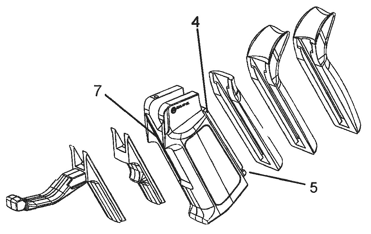
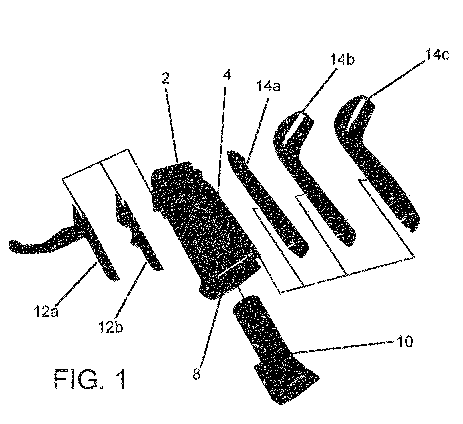
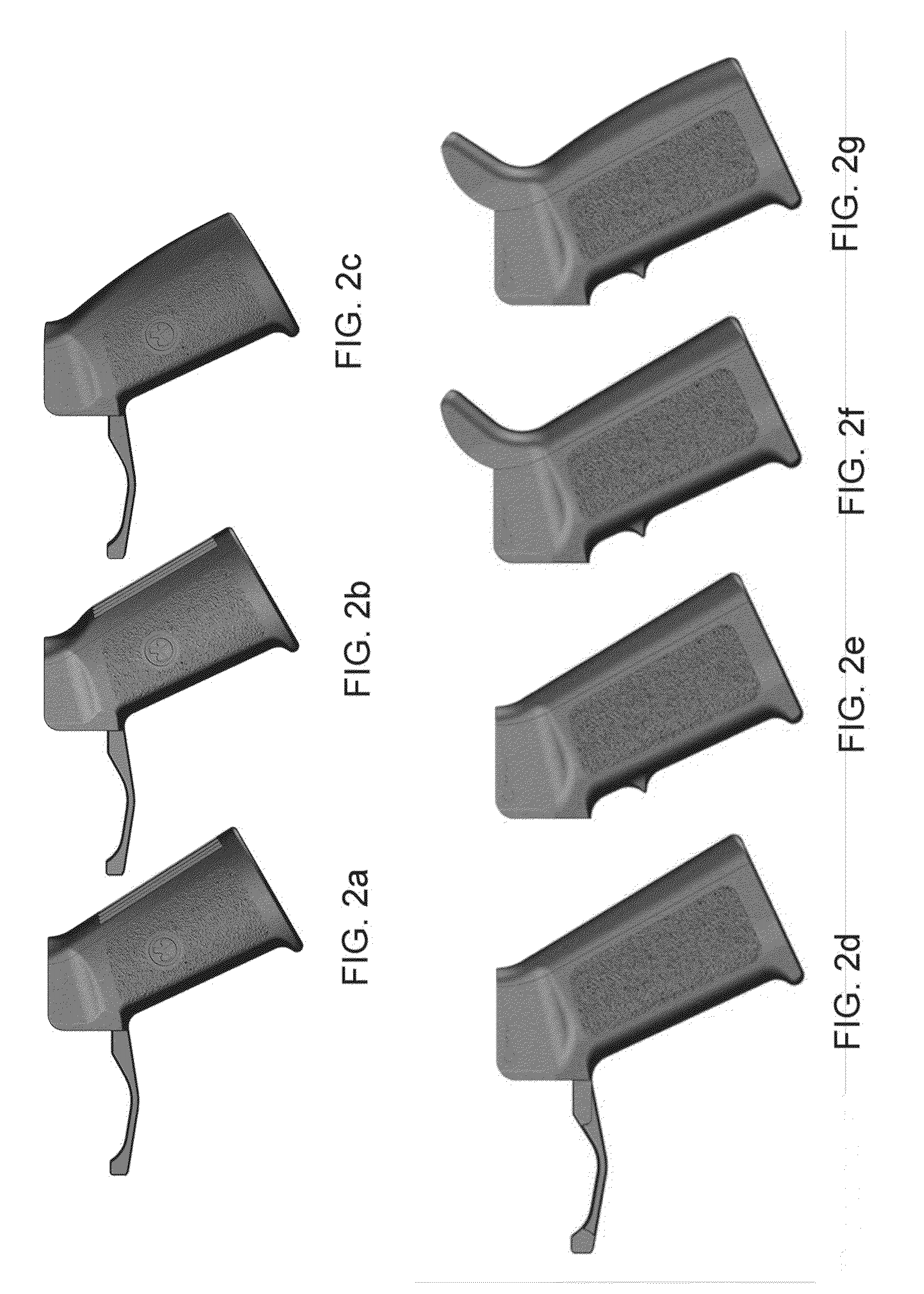
[0021]Referring now to FIGS. 1 and 4, the handgrip comprises a base grip body 2, with an attachment rail 4 and an attachment trough 7. Back straps 14a, 14b and 14c attach to body 2 by sliding unto rail 4 and are secured in place by interfacing with detent 5. Alternatively, a living hinge with a locking tab 20 (as shown in FIGS. 8 and 9) or roll pin may be used to alternately secure the back strap to grip body 2. Locking tab 20 has a tooth that interfaces with ridge 22 to secure the back straps vertically. Rail 4 and body 2 both feature tongue-in-groove manufacture (shown in FIG. 4) to hold either of back straps 14a, 14b, or 14c, in place, shown in FIGS. 3a and 3b. Fore straps 12a, 12b slide into trough 7, locking in...


PUM


Abstract

The present invention is a modular handgrip for rifles and other long guns. The handgrip features a base with a locking dovetail rail on a first side and a second opposite side configured to receive a rail. Back strap additions are provided capable of receiving the rail on the body, which are customizable to a user's preferences while fore straps are provided with rails in a similar manner. Also provided is a storage compartment inside the main body, accessible from a bottom of the grip. As such, an organization, such as an armory, can provide a number of customizable options for handgrips while only stocking a basic grip and a number of optional modules at lower unit and storage costs. Of particular note is a modular fore strap design with an integrated trigger guard.

Description

CROSS-REFERENCES TO RELATE APPLICATIONS[0001]This Application claims priority as a continuation-in-part application of prior filed U.S. application Ser. No. 11 / 381,340, filed May 2, 2006, and incorporates the same by reference in its entiretyFIELD OF THE INVENTION[0002]The present invention relates to handgrips for rifles and more particularly relates to a modular handgrip, which may be modified to the personal preferences of a user.BACKGROUND OF THE INVENTION[0003]Handgrips for rifles are well known in the prior art and are found in many different styles, shapes and designs. Most are not protected by any particular intellectual property protection and most that are have design patents for their ornamental features. Those that have utility patents, or their foreign equivalents, focus on one feature of the handgrip that is novel, like hidden compartments or support tangs. With the variety of handgrips, it becomes very difficult for larger organizations, such as law enforcement and mi...

Claims


Application Information

Patent Timeline
IPC IPC(8): F41C23/14F41C23/22
CPCF41A11/02F41C23/16F41C23/10
Inventor FITZPATRICK, RICHARD M.MAYBERRY, MICHAEL T.
Owner MAGPUL INDUSTRIES
Why Eureka
Try Eureka