Substrate Bonding Apparatus and Substrate Bonding Method

a substrate bonding and apparatus technology, applied in the direction of semiconductor/solid-state device testing/measurement, mechanical control devices, instruments, etc., can solve the problems of alignment errors at a level that cannot always be ignored, complex content of communication/information processing, etc., and achieve high precision

Active Publication Date: 2010-06-10
NIKON CORP
View PDF6 Cites 233 Cited by
  • Summary
  • Abstract
  • Description
  • Claims
  • Application Information

AI Technical Summary

Benefits of technology

[0016]With this method, of ter the positional information that includes the rotational direction within the two-dimensional plane of the first substrate held by the first member is measured, the second substrate is made to be held by the second member that is movable within the two-dimensional plane, and further, the relative position of the second substrate held by the second member with respect to the first substrate held by the first member is adjusted, and thereby both the substrates are bonded. Therefore, taking i

Problems solved by technology

Recently, the contents of communication/information processing have grown complex from character information into images, sounds and animations, and the need to

Method used


Image

  • Substrate Bonding Apparatus and Substrate Bonding Method
  • Substrate Bonding Apparatus and Substrate Bonding Method
  • Substrate Bonding Apparatus and Substrate Bonding Method

Examples


first embodiment

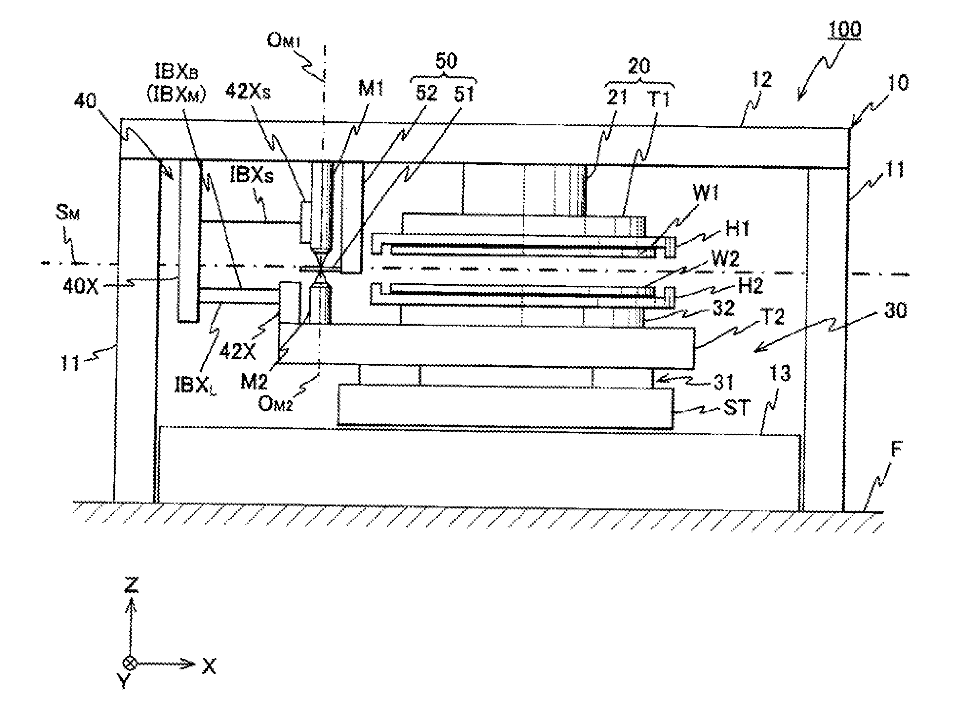
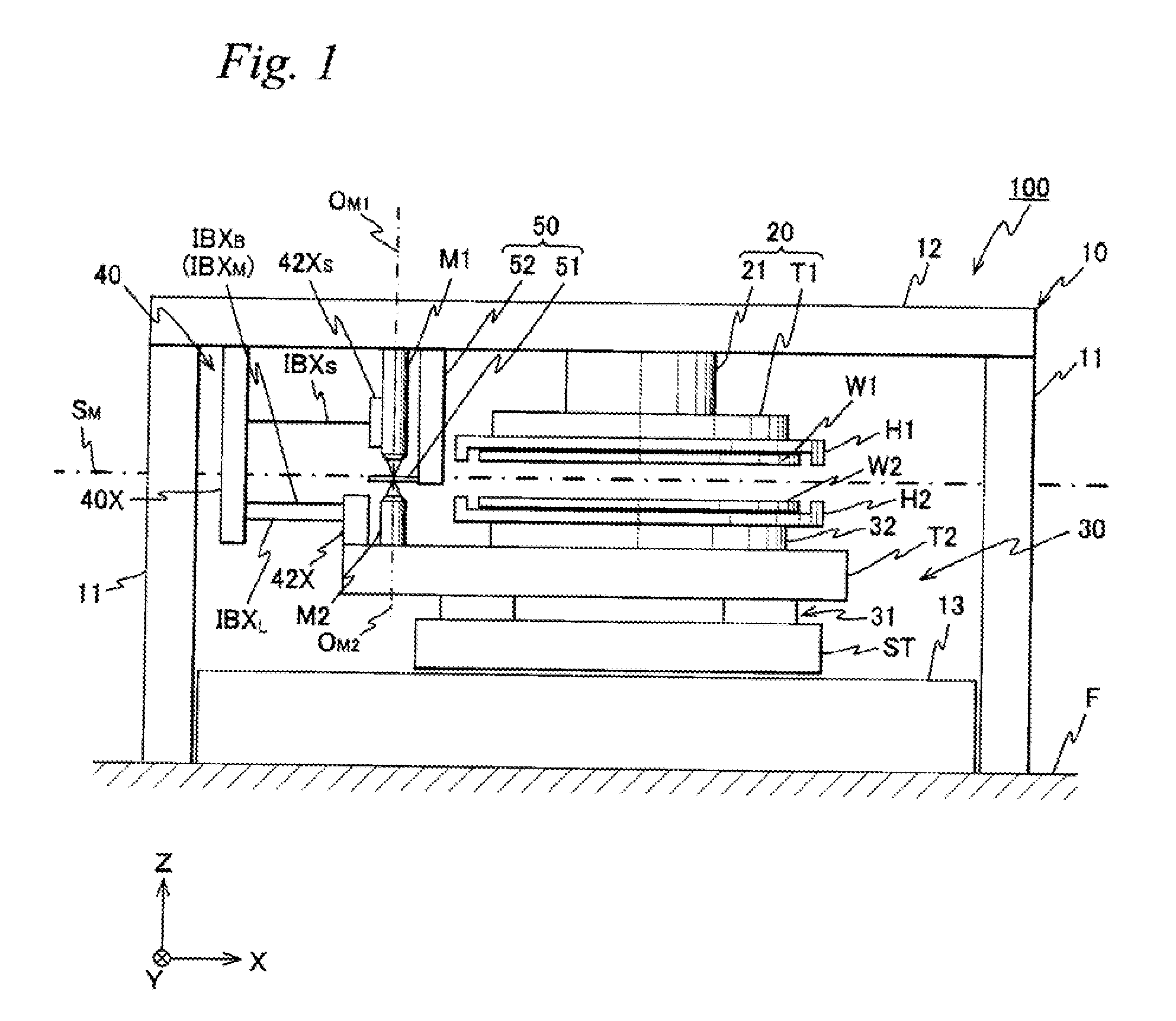
[0048]A first embodiment of the present invention is described below, referring to FIGS. 1 to 14. FIG. 1 schematically shows a configuration of a substrate bonding apparatus 100 related to the first embodiment.

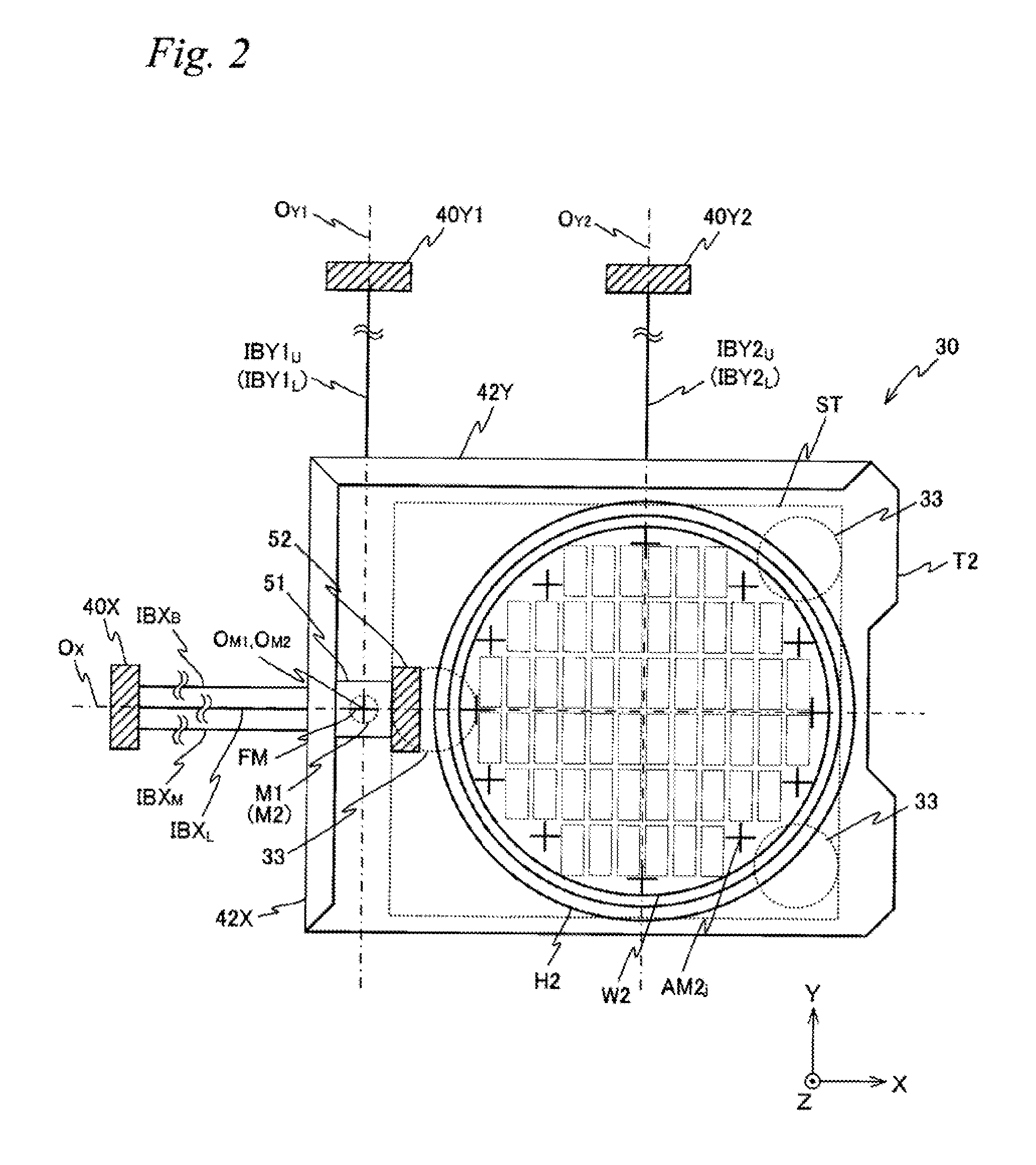
[0049]In substrate bonding apparatus 100, a first mark detection system M1 and an interferometer system 40 are provide (see FIGS. 1 and 2) as is described later on. In the description below, the explanation is given assuming that a direction parallel to an optical axis (which coincides with the detection center) OM1 of first mark detection system M1 is a Z-axis direction, a lateral direction of the page surface of FIG. 1 within a plane orthogonal to optical axis OM1 is an X-axis direction, a direction orthogonal to the page surface is a Y-axis direction, and rotational (tilt) directions around the X-axis, Y-axis and Z-axis are θx, θy and θz directions, respectively. Incidentally, an XY coordinate system with a reference axis OX and a reference axis OY1 within a reference plane...

second embodiment

[0154]Next, a second embodiment of the present invention is described with reference to FIGS. 15 to 25. From the viewpoint of preventing the redundant explanation, regarding the constituents that are the same as or equivalent to those of substrate bonding apparatus 100 related to the first embodiment described above, the same reference sings are used and the explanation thereabout is omitted or simplified in the following description.

[0155]FIG. 15 schematically shows a configuration of a substrate bonding apparatus 200 related to the second embodiment. Substrate bonding apparatus 200 is configured similar to substrate bonding apparatus 100 related to the first embodiment described earlier, except for the placement of a first table device 20 and first mark detection system M1 and configurations of a stage device 230 and an interferometer system 240. Accordingly, in the description below, substrate bonding apparatus 200 is explained, focusing on the differences from substrate bonding ...

third embodiment

[0193]Next, a third embodiment of the present invention is described with reference to FIGS. 26 and 27. Here, regarding the constituents that are the same as or equivalent to those of substrate bonding apparatus 100 of the first embodiment or substrate bonding apparatus 200 of the second embodiment described earlier, the same reference sings are used and also the explanation thereabout is omitted or simplified in the following description.

[0194]FIG. 26 schematically shows a substrate bonding apparatus 300 related to the present third embodiment. In substrate bonding apparatus 300, while configurations of first and second mark detection systems M1 and M2 and placement of some constituents are different from those in the substrate bonding apparatuses of the respective embodiments, the configurations of the other sections, the substrate bonding method and the like are similar to those in the substrate bonding apparatus of the first or second embodiment. Accordingly, in the description ...


PUM

PropertyMeasurementUnit
Speedaaaaaaaaaa
Transparencyaaaaaaaaaa
Distanceaaaaaaaaaa

Abstract

A substrate bonding apparatus is equipped with a first table that holds one wafer of two wafers, a stage device that holds the other wafer in an orientation capable of opposing to the one wafer and that is movable at least within an XY plane, an interferometer system that measures positional information of the stage device within the XY plane, a first mark detection system that can detect subject marks including alignment marks on the other wafer held by the stage device, and a second mark detection system fixed to a part (the second table) of the stage device that can detect subject marks including alignment marks on the one wafer held by the first table.

Description

CROSS-REFERENCE TO RELATED APPLICATIONS[0001]This application is a continuation of International Application PCT / JP2008 / 002146, with an international filing date of Aug. 7, 2008, the disclosure of which is hereby incorporated herein by reference in its entirety, which was not published in English.BACKGROUND OF THE INVENTION[0002]1. Field of the Invention[0003]The present invention relates to substrate bonding apparatuses and substrate bonding methods, and more particularly, to a substrate bonding apparatus and a substrate bonding method to align and bond two substrates.[0004]2. Description of the Background Art[0005]Recently, the contents of communication / information processing have grown complex from character information into images, sounds and animations, and the need to transmit and process information of large volumes at high speed arises. Therefore, in the field of manufacturing mobile type electronic appliances such as cell phones, notebook-sized personal computers, audio equ...

Claims


Application Information

Patent Timeline
IPC IPC(8): B29C65/00B29C65/78
CPCH01L21/67092H01L21/68H01L23/544H01L2223/5442H01L2223/54426H01L2223/54453H01L2924/0002H01L2223/54493H01L22/12H01L2924/00
Inventor HORIKOSHI, TAKAHIRO
Owner NIKON CORP
Why Eureka
Try Eureka