Air cushion landing system and method of operation

a technology of air cushion and landing system, which is applied in the direction of floats, jet propulsion plants, rigid airships, etc., can solve the problems of increasing the weight, complexity and cost of hybrid aircraft, and increasing the weight of components and thereby making undesirable heavy. , to achieve the effect of rapid reversal of flow

Inactive Publication Date: 2010-06-10
AIR CUSHION LANDING SYST
View PDF10 Cites 6 Cited by
  • Summary
  • Abstract
  • Description
  • Claims
  • Application Information

AI Technical Summary

Benefits of technology

[0007]Such a system reduces the shock on the aircraft during a landing event by using the plenum fan and ducting, which is already part of the aircraft equipment thereby and avoiding the need to incorporate venting valves and associated ducting. Furthermore, the plenum fan in an aircushion landing system is, by necessity, a high capacity fan capable of delivering a high flow of air. Accordingly, its use to evacuate the plenum as touchdown occurs, and for a period thereafter, very effectively reduces the shock imparted to the aircraft. Also, the area of ducting through which venting occurs will be considerably smaller than that which would be required if valves were employed as a result of the assistance given to the evacuation by the fan prior to and during touchdown.
[0012]Advantageously the fan control system includes means for subsequently controlling the plenum fan so as to reverse the flow of air in order that it flows in an opposite second direction to thereby increase plenum pressure to raise the aircraft. Such a system permits significant collapsing of the plenum to occur, thus spreading the time and distance over which the arresting of downward movement of the aircraft can be effected. The plenum fan is also used to bring the aircraft up to the desired level for taxiing and mooring.
[0013]Preferably the plenum fan includes means for varying, including reversing, fan blade pitch actuated by means of the fan control system. This provides a very rapid and easily controllable way of varying the flow induced / allowed by the plenum fan.
[0014]Preferably the fan control also includes means for controlling rotation speed of the fan. This provides two parameters (speed and blade pitch) which can be balanced to provide the required flow and operate with minimum power consumption. After the fan has acted to restrict flow in the first direction (out of the plenum) caused by downward momentum of the aircraft compressing the plenum, the fan changes its function and it is operated to induce a flow in the second opposite direction to pressurise the plenum and thereby raise the aircraft.
[0019]More preferably the method also includes the subsequent step of:(iv) controlling operation of the plenum fan with the fan control system so as to reverse the flow of air in order that it flows in an opposite second direction into the plenum thereby increasing plenum pressure to raise the aircraft.
[0020]Conveniently, controlling of the operation of the fan is effected by means of controlling at least one of plenum fan rotation rate and plenum fan blade pitch. Very rapid reversal of the flow can be effected by reversing the fan blade pitch. It is also envisaged that aerodynamic performance of the fan may be adjusted by altering other aspects of its geometry.

Problems solved by technology

One problem that has been encountered with air cushion landing systems for hybrid aircraft is that when a high level of sink landing occurs and the skirt forms a good seal at its point of engagement, the severe shock that is imparted to the hybrid aircraft is a major design consideration and may result in components being strengthened and thereby made undesirably heavy.
Firstly, venting the plenum in this manner may not act quickly enough so the shock loading on the aircraft is not sufficiently reduced.
Secondly, the valves constitute additional components which add to the weight, complexity and cost of the hybrid aircraft.
Thirdly, the cross-sectional area of ducting required to provide a significant venting capability is very large because air is only vented under the influence of the pressure differential existing between the plenum and the ambient atmosphere.
Large ducts for such a purpose add still further weight, complexity and cost and can impinge on cargo storage space in the hybrid aircraft.

Method used


Image

  • Air cushion landing system and method of operation
  • Air cushion landing system and method of operation
  • Air cushion landing system and method of operation

Examples


Embodiment Construction

)

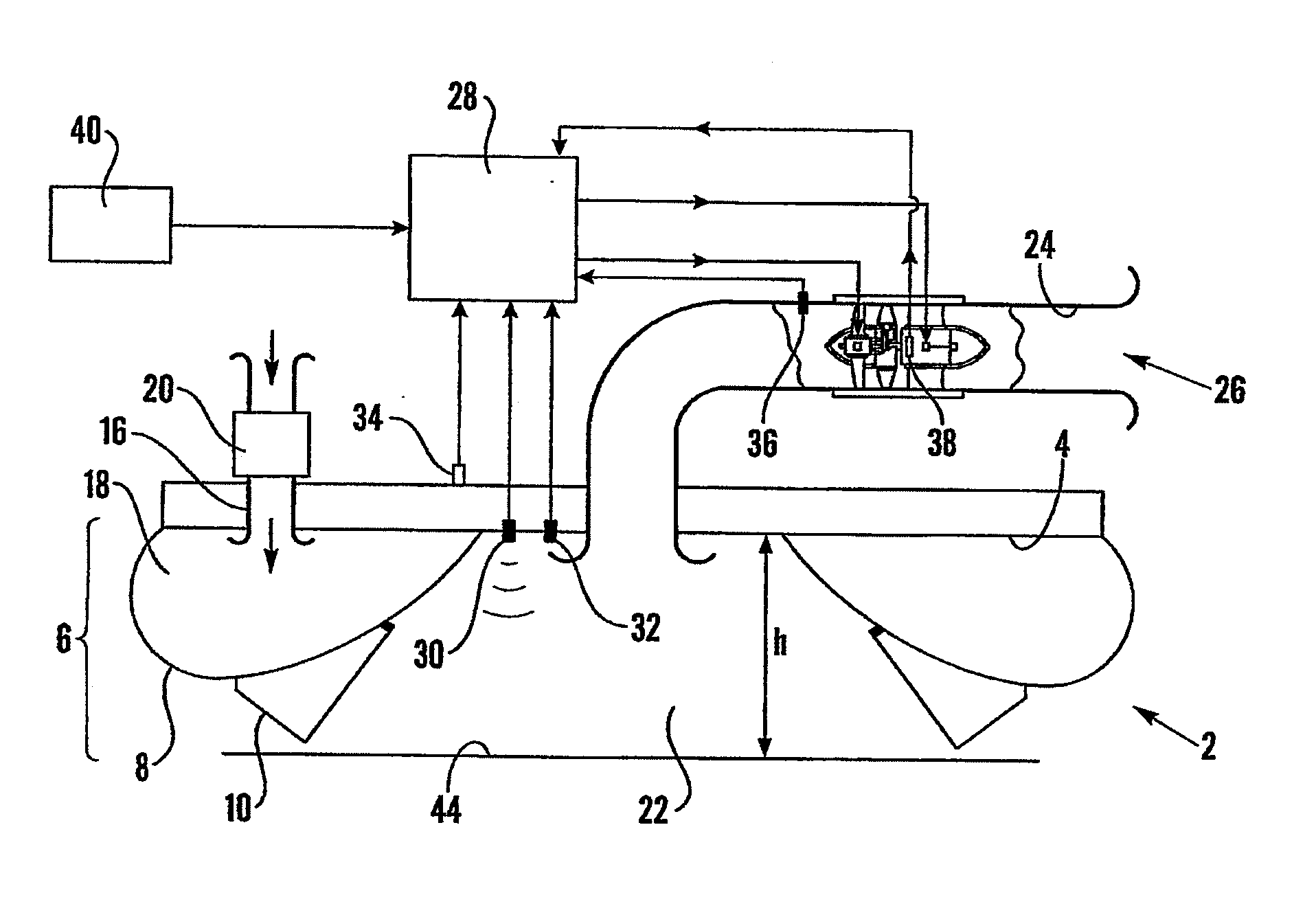
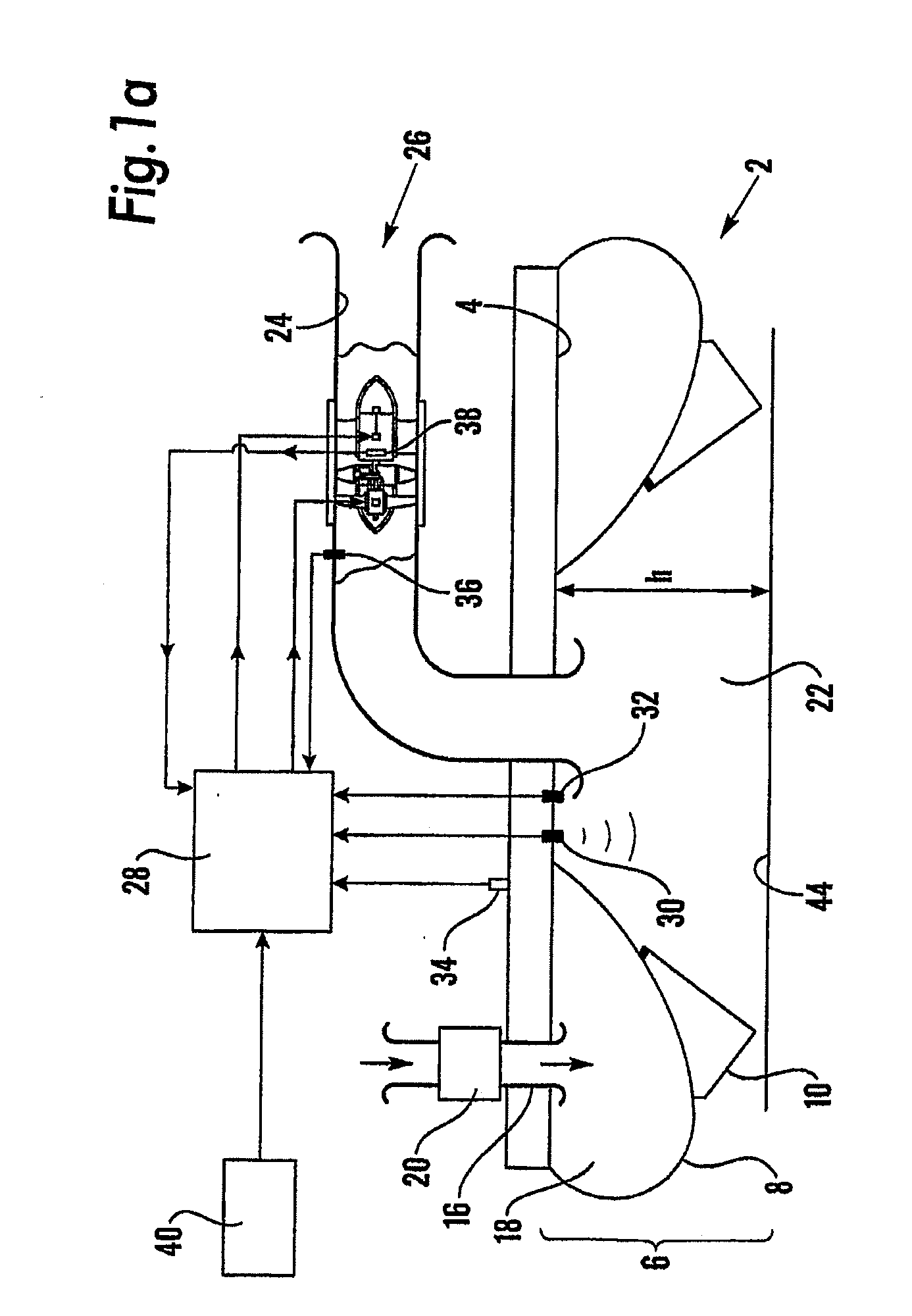
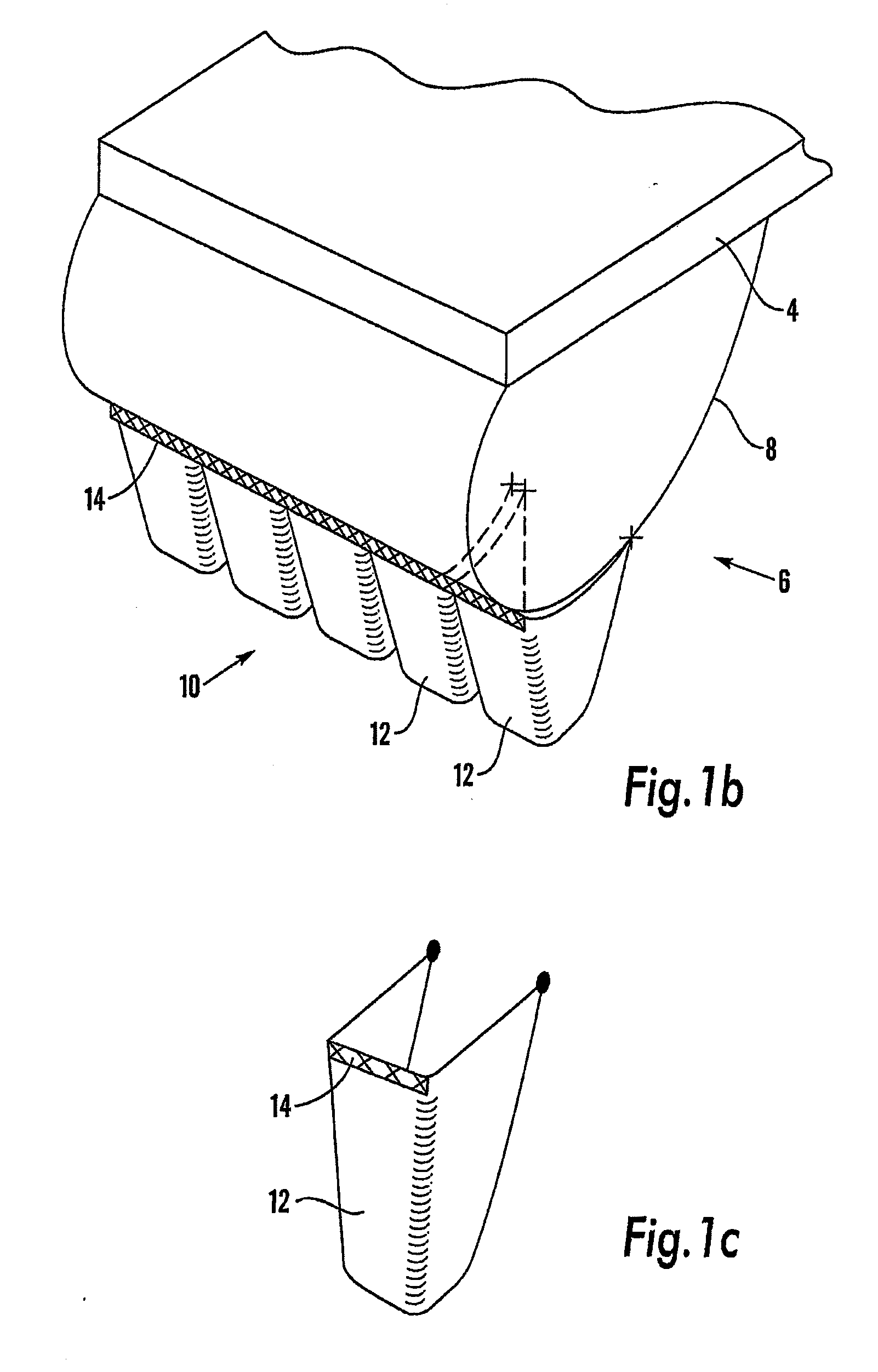
[0033]FIG. 1a shows an aircraft air cushion landing system 2 in accordance with the invention. An annular skirt 6 is connected to lower surface 4 of a fuselage of the aircraft. The skirt 6 comprises an annular inflatable skirt 8 to a bottom of which a finger skirt 10 is attached. As shown in FIG. 1b, the finger skirt 10 is composed of individual fingers 12, one of which is shown in isolation in FIG. 1c. Each finger 12 is attached to the inflatable skirt 8 with fixing means such as sewing 14. Lower portions of adjacent fingers 12 are not connected to each other so that the fingers may be displaced individually or in groups to allow the finger skirt 10 to easily pass over objects. A skirt duct 16 connects a skirt fan 20 to an interior 18 of the inflatable skirt 8. A plenum 22 is bounded and defined by the skirt 6 and a plenum fan 26 is connected to the plenum 22 by a plenum duct 24.

[0034]A control module 28 is provided for controlling the operation of the plenum fan 26 and receives i...


PUM


Abstract

An aircraft air cushion landing system (2) includes a skirt (6) defining a plenum (22) on an underside of the aircraft, a plenum fan (26) arranged to induce an airflow into the plenum (22) and controller configured to control operation of the plenum fan (26). The controller includes a sensor (30) adapted to sense an imminent landing event and a fan control system (28) configured to automatically operate the plenum fan (26) to provide a first flow in a first direction out of the plenum (22) so that as the skirt (6) engages a landing surface air is being evacuated from the plenum (22). A method also operates such a system (2).

Description

[0001]This application is a Continuation-in-Part of International Application No. PCT / GB2008 / 050196, filed 19 Mar. 2008, which claims benefit of Serial No. 0705642.7, filed 23 Mar. 2007 in Great Britain and which applications are incorporated herein by reference. To the extent appropriate, a claim of priority is made to each of the above disclosed applications.FIELD OF THE INVENTION[0002]The present invention relates to an aircraft air cushion landing system and a method of operating one. More particularly, the invention relates to such a system and method for a hybrid aircraft employing a combination of buoyancy and aerodynamic lift for flying.BACKGROUND OF THE INVENTION[0003]Conventional wheeled undercarriages are not suitable for use with hybrid aircraft and so-called air cushion landing systems have been proposed as an alternative. Such air cushion landing systems include one or more plenum chambers, each plenum chamber being surrounded by a skirt, having an open under surface a...

Claims


Application Information

Patent Timeline
Patent Type & Authority Applications(United States)
IPC IPC(8): B64C25/32F02K1/00B64B1/20
CPCB60V3/08
Inventor LONDON, RUSSELL JOHNCOX, MALCOLM JOHN
Owner AIR CUSHION LANDING SYST
Why Eureka
Try Eureka