

Illumination apparatus
- Summary
- Abstract
- Description
- Claims
- Application Information
AI Technical Summary
Benefits of technology
Problems solved by technology
Method used
Image

Examples
first embodiment
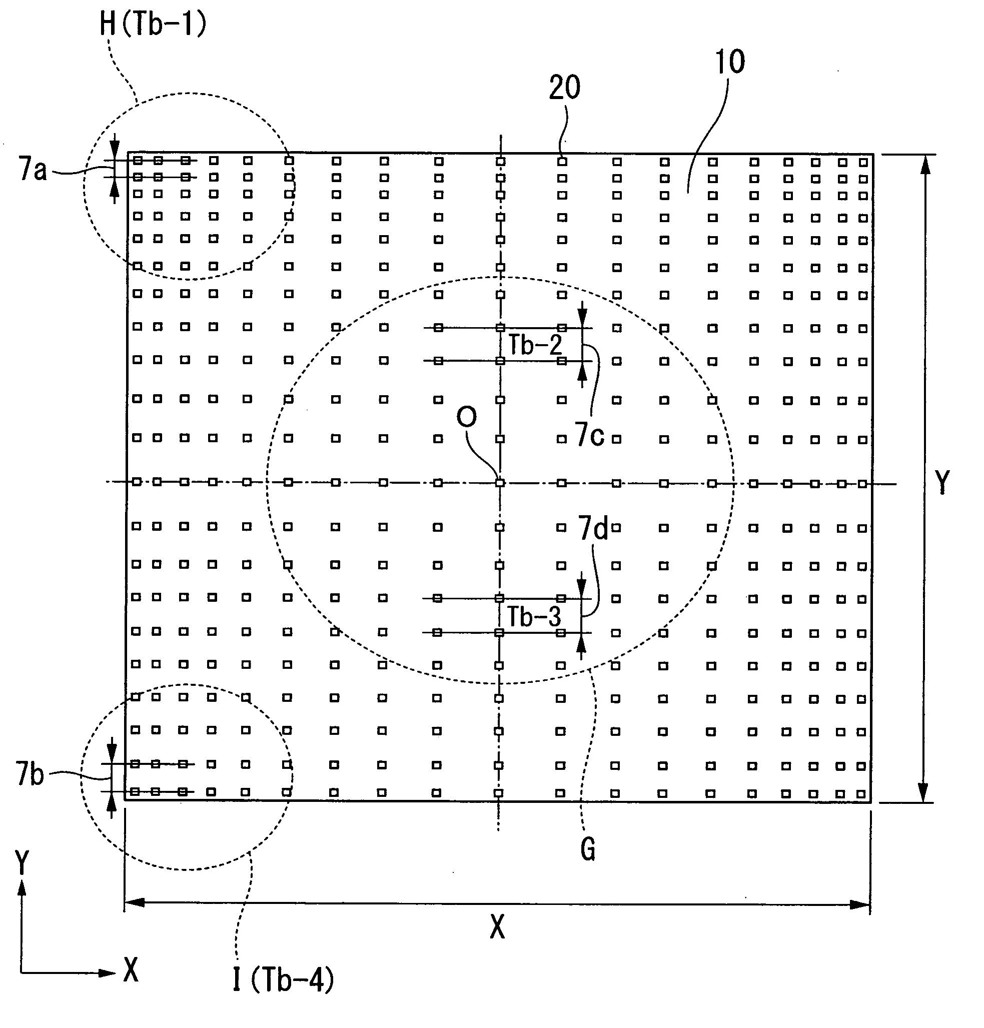
[0036]FIG. 6 is a cross-sectional view showing an outline of the liquid crystal display device appropriately using an illumination device for the non-light emission transparent display devices of this invention. In the explanation below, the LED (Light Emitting Diode) part 20 is an element which has packaged within the same package a red color LED, green color LED, and blue color LED.
[0037]Along with a plurality of LED parts 20 which are arranged two dimensionally, reflecting material 30 is provided on the upper part of a base material 10, reflecting light which radiated from the LED parts 20 at the peripheral edge of the base material 10 and a diffusion plate 40 is provided on the base material 10 and on the upper part of a parallel surface by the reflection material 30. This base material 10 has a substantially uniform thermal conductivity across its entire surface.
[0038]A wire is provided on the base material 10 to supply to each of the LED parts 20 a drive current supplied from ...
second embodiment
[0124]FIG. 10 is an outline cross-sectional view of the display device 200 which is one example of a liquid crystal display device appropriate for use with an illumination apparatus used for a non-light emission display device according to a
[0125]This display device 200 is formed as a laminate, laminating in order, a reflection material 230, a photoconductive plate 240, an optical film 250, and a liquid crystal panel 260. By irradiating light from LED parts 220 provided on a base material 210, a liquid crystal panel 260 is illuminated.
[0126]A plurality of LED parts 20 are arranged in a straight line. Along with the thermal conductivity for the base material 210 being made uniform along the entire surface, wires are provided for supplying to the LED parts 220 drive current from the drive section which outputs drive current in order to cause the LED parts 220 to emit light.
[0127]The LED parts 220 irradiate light from the side of the liquid crystal panel 260. The light irradiated from ...
PUM
 Abstract
Description
Claims
Application Information