Optical line terminal, passive optical network and radio frequency signal transmission method

a passive optical network and optical line terminal technology, applied in the field of network communication, can solve the problem of low achieve the effect of enhancing the bandwidth of wireless access network, enhancing the power spectrum of modulation signal, and reducing the cost of operation

Inactive Publication Date: 2010-06-10
HUAWEI TECH CO LTD
View PDF14 Cites 157 Cited by
  • Summary
  • Abstract
  • Description
  • Claims
  • Application Information

AI Technical Summary

Benefits of technology

[0015]It can be seen from the description of the above technical solution that, by combining one dedicated downstream optical carrier and two dedicated upstream optical carriers for an ONU, wavelength division multiplexing each combined downstream optical carrier and then transmitting them, on the basis of realizing a colorless ONU, the optical carrier may carry more signals, the large-capacity bandw...

Problems solved by technology

Nevertheless, the above prior RF signal transmission has at least the following problems:
Therefore, the large-capacity ba...

Method used


Image

  • Optical line terminal, passive optical network and radio frequency signal transmission method
  • Optical line terminal, passive optical network and radio frequency signal transmission method
  • Optical line terminal, passive optical network and radio frequency signal transmission method

Examples


Embodiment Construction

[0022]A passive optical network according to an embodiment of the present disclosure is described below.

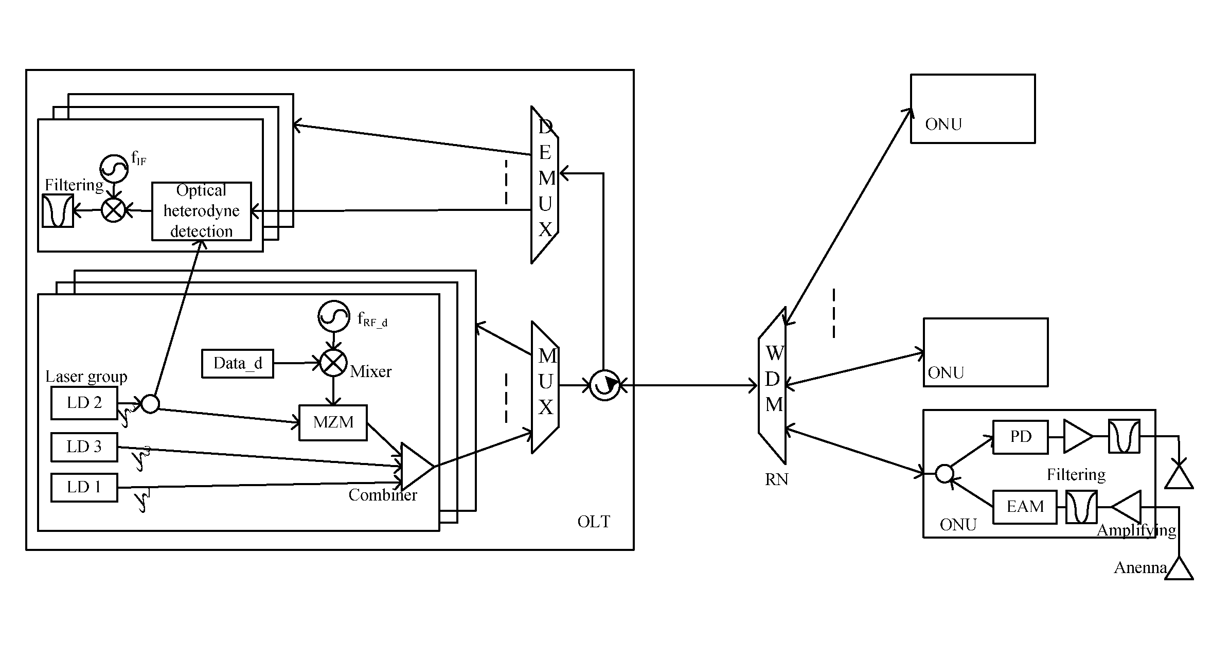
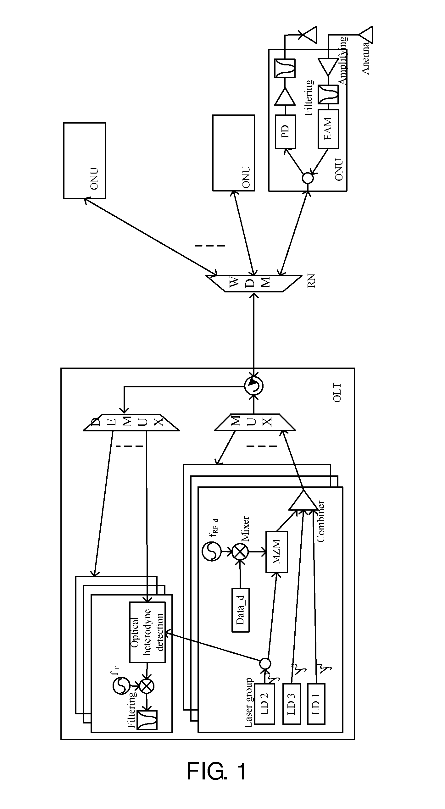
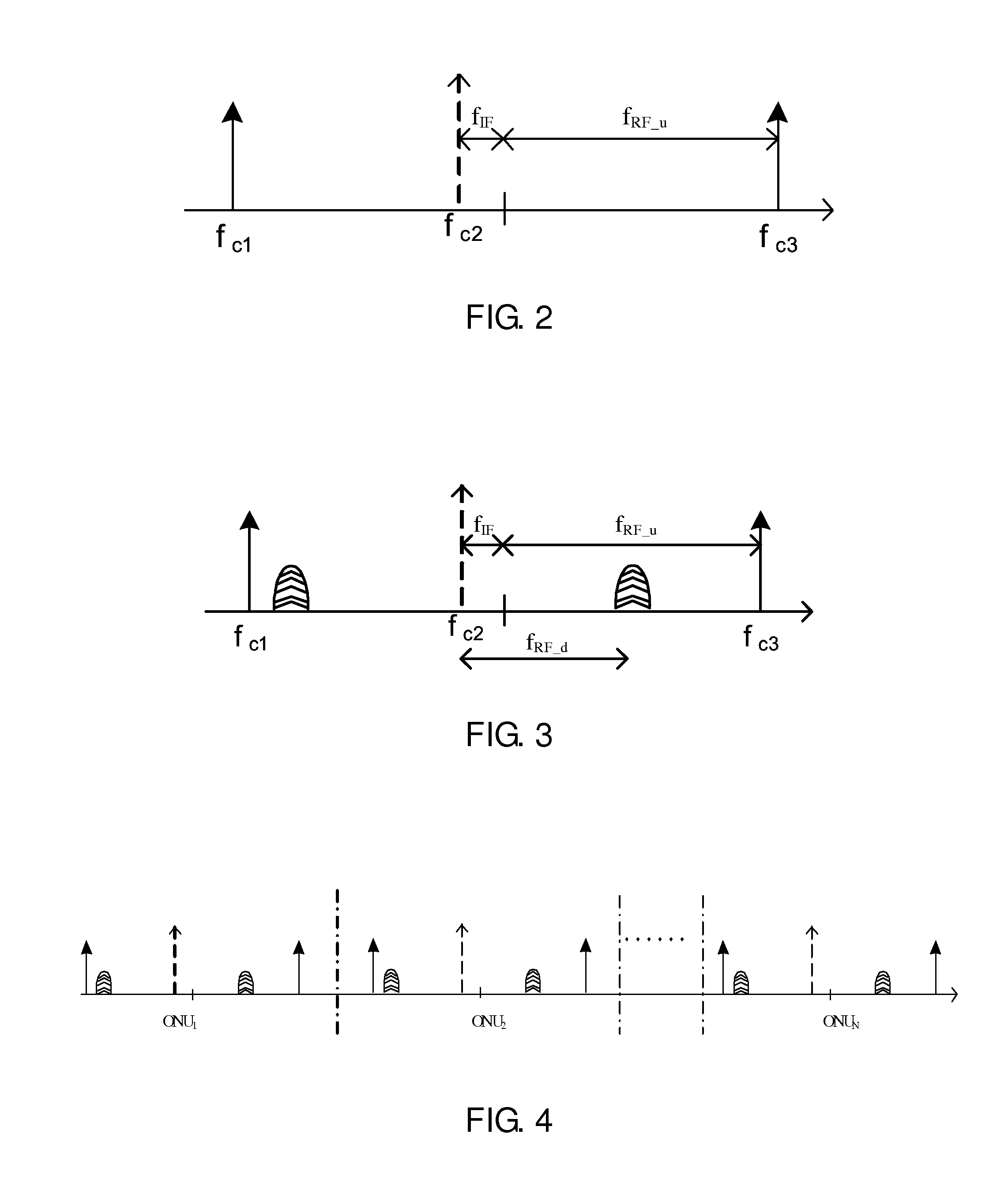
[0023]The passive optical network according to an embodiment of the present disclosure includes: an Optical Line Terminal (OLT), an Optical Distribution Network (ODN), and at least one Optical Network Unit (ONU). Generally, there is a plurality of ONUs. The ONU has dedicated optical carriers; that is, each ONU correspondingly has dedicated optical carriers, one ONU having two dedicated upstream optical carriers and one dedicated downstream optical carrier.

[0024]The OLT includes: a transmitting unit, a multiplexing / demultiplexing unit and a receiving unit. There are one or more transmitting units and one or more receiving units. One transmitting unit corresponds to one ONU, and one receiving unit corresponds to one ONU. The number of the transmitting units and the number of the receiving units may be related to that of an ONU.

[0025]The process of transmitting, by OLT, the downstr...


PUM


Abstract

An optical line terminal, a passive optical network and a radio frequency signal transmission method in the communication technical field are provided. The passive optical network comprises: an OLT, an ODN and at least one ONU. The OLT comprises: at least one transmitting unit, which provides one dedicated downstream optical carrier and two dedicated upstream optical carriers for ONU; the two dedicated optical carriers for ONU are configured to carry ONU upstream radio frequency signals; a multiplexing/demultiplexing unit; and at least one receiving unit which obtains the upstream signal from the demultiplexed upstream optical signal. The bandwidth of wireless access network is enhanced, and the design of ONU is simple.

Description

CROSS-REFERENCE TO RELATED APPLICATIONS[0001]This application is a continuation of International Application No. PCT / CN2008 / 072466, filed on Sep. 23, 2008, which claims priority to Chinese Patent Application No. 200710122523.3, filed on Sep. 26, 2007, both of which are hereby incorporated by reference in their entireties.FIELD OF INVENTION[0002]The present disclosure relates to the technical field of network communications, and more particularly to an optical line terminal, a passive optical network and a radio frequency signal transmission method.BACKGROUND OF THE INVENTION[0003]A Passive Optical Network (PON) is a point-to-multipoint tree network structure. With such characteristics as simple network structure, sharing optical fiber resources, low cost and no need for installing active equipment externally, The PON is recognized as the most promising optical access technology.[0004]At present, in the network based on a PON, the Radio Frequency (RF) signal transmission method is as...

Claims


Application Information

Patent Timeline
IPC IPC(8): H04J14/02
CPCH04B10/25754H04B10/2587H04J14/0227H04J14/0282H04J14/0265H04J14/0246H04J14/025H04J2014/0253H04J14/0298
Inventor YU, FANZHAO, JUN
Owner HUAWEI TECH CO LTD
Why Eureka
Try Eureka