
Systems and methods for assembling a pitch assembly for use in a wind turbine

a technology of wind turbine and assembly system, which is applied in the direction of machines/engines, rotors, final product manufacturing, etc., can solve the problems of inability of the pitch drive system to rotate the blade, the blade teeth of the bearing may become worn, and the pitch drive system becomes less effective in operating to adjust the pitch of the blades

Inactive Publication Date: 2010-06-10
GENERAL ELECTRIC CO
View PDF12 Cites 31 Cited by
  • Summary
  • Abstract
  • Description
  • Claims
  • Application Information

AI Technical Summary

Benefits of technology

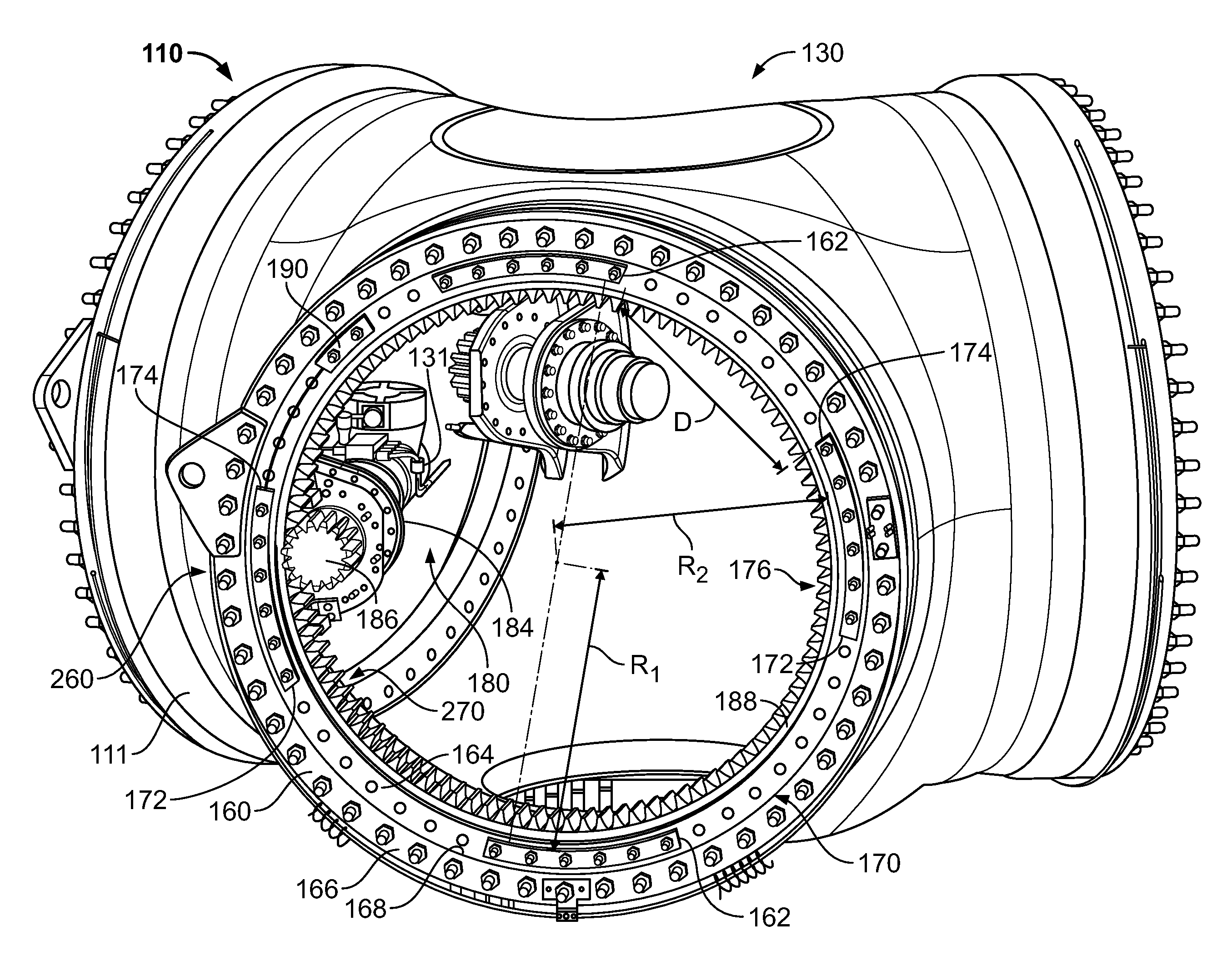
[0008]The embodiments described herein facilitate adjusting the pitch drive system without requiring the hub and / or rotor to be removed from the wind turbine. More specifically, the pitch assembly described herein enables a blade to be selectively rotated relative to the pitch bearing such that the pitch drive can engage new pitch bearing teeth without removing the hub and / or rotor from the wind turbine.

Problems solved by technology

Over time, the pitch bearing teeth of the bearing may become worn.
As the pitch bearing teeth become worn, the pitch drive system becomes less effective in operating to adjust the pitch of the blades.
In some cases, the pitch bearing teeth can fail resulting in the inability of the pitch drive system to rotate the blade.
In some wind turbines, the blades are between 60 and 100 meters in length, and as such, replacing bearings with worn teeth can be costly and time-consuming.
During operation, worn pitch bearing teeth may enable a blade to undesirably move from a desired pitch setting.
In some cases, the blades of the wind turbine asymmetrically load the hub and rotor shaft, and may cause the rotor to become imbalanced.
Depending on the extent of the rotor imbalances, increased loads may be induced to the rotor and other drive train components.
Moreover, the rotor's position with respect to the wind may induce increased loads on the rotor and other drive train components.

Method used


Image

  • Systems and methods for assembling a pitch assembly for use in a wind turbine
  • Systems and methods for assembling a pitch assembly for use in a wind turbine
  • Systems and methods for assembling a pitch assembly for use in a wind turbine

Examples


Embodiment Construction

[0014]The embodiments described herein include a wind turbine system that enables the maintenance of the pitch bearing assembly without requiring the hub and / or rotor of the wind turbine to be removed. More specifically, the pitch assembly described herein enables the pitch drive to be moved to engage new pitch bearing teeth.

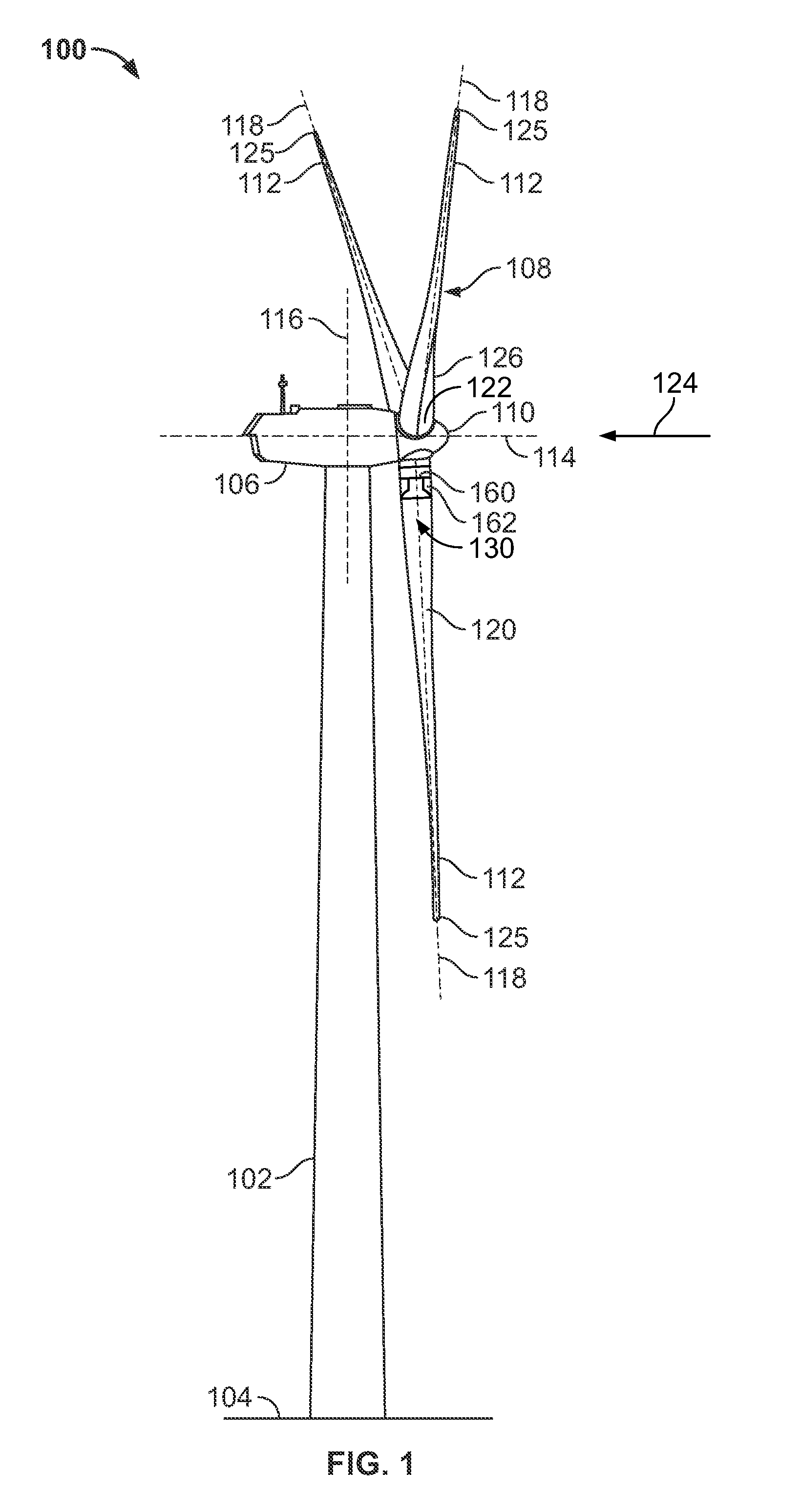
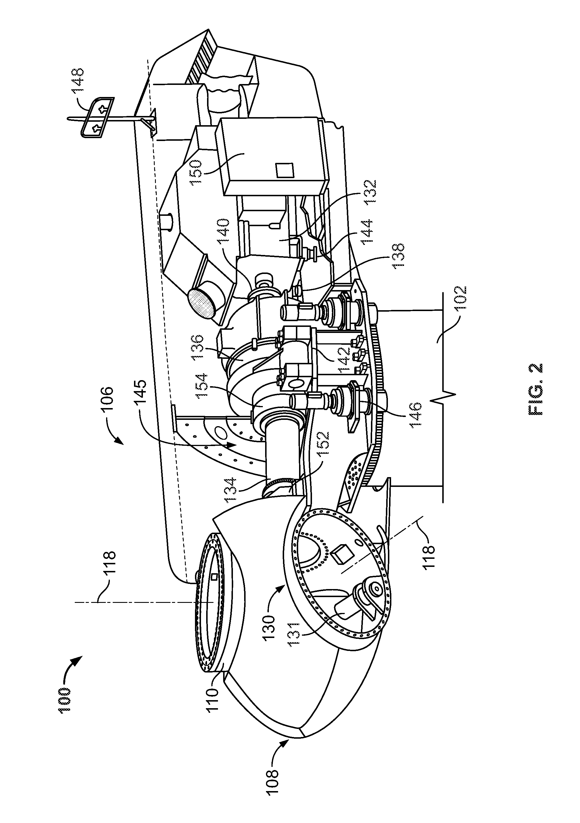
[0015]As used herein, the term “blade” is intended to be representative of any device that provides a reactive force when in motion relative to a surrounding fluid. As used herein, the term “wind turbine” is intended to be representative of any device that generates rotational energy from wind energy, and more specifically, converts kinetic energy of wind into mechanical energy. As used herein, the term “wind generator” is intended to be representative of any wind turbine that generates electrical power from rotational energy generated from wind energy, and more specifically, converts mechanical energy converted from kinetic energy of wind to electrical power.

[0...


PUM


Abstract

A method of assembling a pitch assembly for use in a wind turbine. The method includes coupling a pitch bearing to a hub of the wind turbine, wherein the pitch bearing includes a plurality of bearing teeth. A pitch drive system is coupled to the pitch bearing such that the pitch drive system contacts a first set of bearing teeth. A plurality of bearing segments is coupled to the pitch bearing to cause the pitch drive system to selectively contact a second set of bearing teeth.

Description

BACKGROUND OF THE INVENTION[0001]The embodiments described herein relate generally to methods and systems for assembling a wind turbine including a pitch system, and more particularly, to systems and methods for assembling a pitch assembly for use in wind turbines.[0002]At least some known wind turbines include a bearing coupled between a blade and a hub, and a pitch drive system for use in positioning the blade attached to the bearing. The pitch drive system is operated to adjust the pitch of the blade. Over time, the pitch bearing teeth of the bearing may become worn. As the pitch bearing teeth become worn, the pitch drive system becomes less effective in operating to adjust the pitch of the blades. In some cases, the pitch bearing teeth can fail resulting in the inability of the pitch drive system to rotate the blade. In at least some known wind turbines the entire hub and rotor must be removed from the wind turbine, prior to removing each blade and adjusting the pitch bearing to...

Claims


Application Information

Patent Timeline
IPC IPC(8): F03D7/02B23P11/00
CPCF03D7/0224F03D11/0008F05B2230/60F05B2240/50Y10T29/49316F05B2260/79Y02E10/722Y02E10/723F05B2260/70F03D80/70Y02E10/72Y02P70/50
Inventor DANIELS, JEFFREY MICHAELKORIM, DAVID CHARLES
Owner GENERAL ELECTRIC CO
Learn More