Ion pump device

a technology of ion pump and ion pump, which is applied in the direction of machines/engines, liquid fuel engines, positive displacement liquid engines, etc., can solve the problems of unidirectional magnetic fields, ineffective utilization of space in ion pump, and pollution of semiconductor surface by gas molecules, etc., to achieve efficient magnetic fields, light weight, and high efficiency

Active Publication Date: 2010-06-10
NAT INST OF INFORMATION & COMM TECH
View PDF5 Cites 2 Cited by
  • Summary
  • Abstract
  • Description
  • Claims
  • Application Information

AI Technical Summary

Benefits of technology

[0011]It is an object of the present invention to provide a lightweight ion pump.
[0033]According to the present invention, as electric fields are efficient three-dimensional electric fields and a magnet is divided into a plurality of cylindrical magnets which are located at predetermined intervals, a lightweight ion pump with a simple structure can be provided.

Problems solved by technology

Surfaces of semiconductors are subject to pollution by gas molecules.
For this reason, the magnetic fields are unidirectional, and the spaces in the ion pumps have not been able to be effectively utilized.
However, such ion pumps need to use many insulators such as ceramics in order to obtain insulation between electrodes.
For this reason, there is a problem that gases are emitted from ceramics etc., lowering a degree of vacuum.
There is also a problem that such ion pumps do not have enough strength.
Furthermore, such ion pumps are large and heavy, and their power consumption is also large.
Therefore, there is a problem that once the conventional ion pumps are located they cannot be moved easily.

Method used


Image

  • Ion pump device
  • Ion pump device
  • Ion pump device

Examples


embodiment 1

[0071]Prototypes of an ion pump and a vacuum carrying device concerning the present invention were manufactured. FIG. 9 is a photograph replacing a drawing showing the actually manufactured vacuum carrying device.

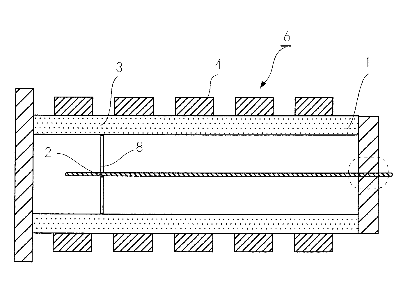
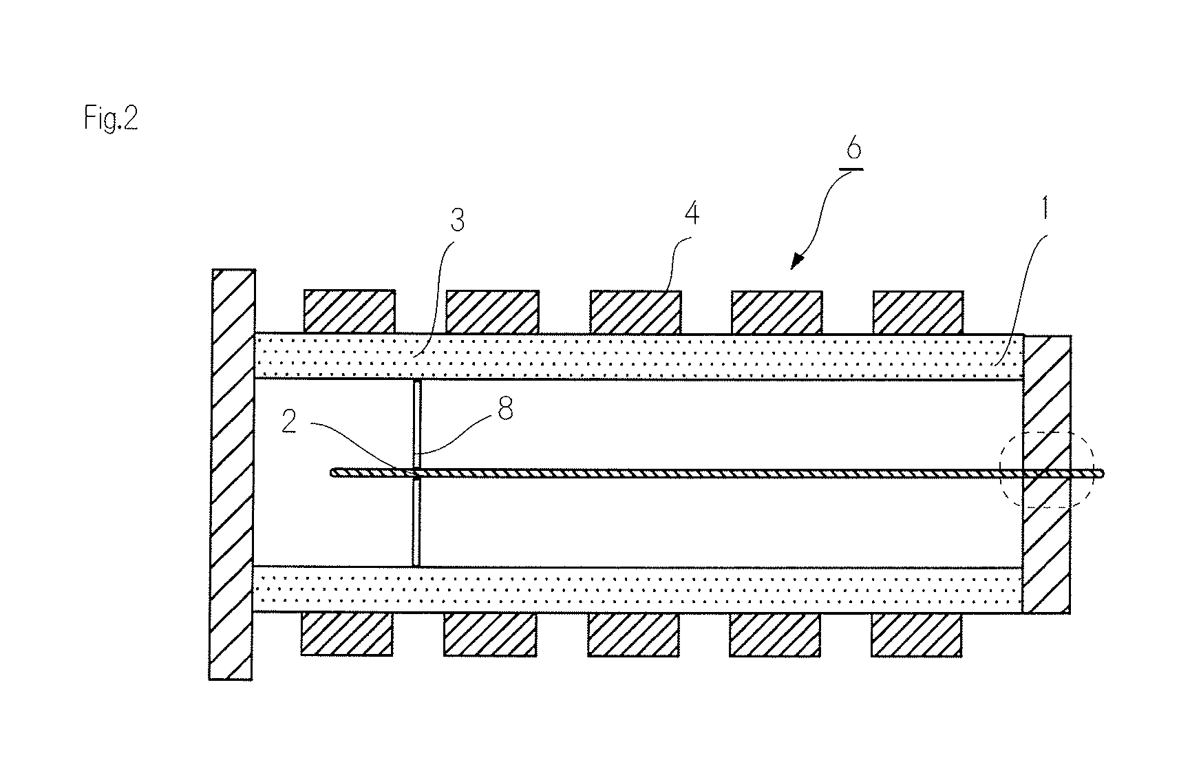
[0072]In this ion pump, five ring-like permanent magnets are located at equal intervals in the circumference of the casing which concurrently serves as the second electrode. In this vacuum carrying device, the frame was formed with aluminum having aluminum oxide film. Moreover, in another vacuum carrying device, the frame was formed with titanium having titanium dioxide film. A 2.75″ gate valve having a 1.33″ routing port was used as a gate valve. An up-and-down clamp having a bellow was used as a sample lock. Batteries were used as a power supply. Moreover, a vacuum meter was located for measuring the degree of vacuum in the sample room

[0073]This vacuum carrying device could locate samples with a maximum diameter of 35 mm. Moreover, high vacuum with internal pressure of 1×...


PUM


Abstract

The above-mentioned problem is solved by an ion pump (6) comprising a casing (1), a first electrode (2), a second electrode (3), a plurality of cylindrical magnets (4), and a connection part (5). The first electrode (2) is arranged inside the casing (1). The second electrode (3) is arranged on the outer circumference of the first electrode (2). The first electrode and the second electrode have different polarities. The cylindrical magnets (4) are arranged so as to surround the circumference of the second electrode (3). The plurality of cylindrical magnets (4) are arranged so as to surround the circumference of the second electrode (3). The plurality of cylindrical magnets (4) are arranged at intervals in the center axis direction of the casing (1).

Description

TECHNICAL FIELD[0001]The present invention relates to an ion pump device etc. so miniaturized as to be carried by introducing three-dimensional magnetic fields.BACKGROUND ART[0002]With the development of nanotechnology and ultra-precision measuring technologies, ultrahigh vacuum technologies have been emphasized. Surfaces of semiconductors are subject to pollution by gas molecules. In contrast, by maintaining semiconductors in an ultrahigh vacuum below about 10−7 Pa, the surfaces of semiconductors can be kept clean. And pumps such as an ion pump are used to maintain an ultrahigh vacuum.[0003]As shown in FIGS. 4(A) and 4(B) in Japanese Patent Application Laid-Open No. H9-27294, for example, conventional ion pumps have arranged tabular permanent magnets so as to face each other in parallel across a cuboid container. For this reason, the magnetic fields are unidirectional, and the spaces in the ion pumps have not been able to be effectively utilized.[0004]In order to solve such a probl...

Claims


Application Information

Patent Timeline
Patent Type & Authority Applications(United States)
IPC IPC(8): H01J41/18
CPCH01J41/12
Inventor TANAKA, SHUKICHI
Owner NAT INST OF INFORMATION & COMM TECH
Why Eureka
Try Eureka